UNIVERSITI TEKNIKAL MALAYSIA MELAKA
SURFACE MODIFICATION OF LOW CARBON STEEL IN LASER
CUTTING
This report submitted in accordance with requirement of the Universiti Teknikal
Malaysia Melaka (UTeM) for the Bachelor Degree of Manufacturing Engineering
(Manufacturing Process) with Honours.
by
UNIVERSITI TEKNIKAL MALAYSIA MELAKA
BORANG PENGESAHAN STATUS LAPORAN PROJEK SARJANA MUDA
TAJUK: Surface Modification of Low Carbon Steel in LASER Cutting
SESI PENGAJIAN: 2008/09 Semester 2
Saya LUEI HONG KEAT
mengaku membenarkan Laporan PSM ini disimpan di Perpustakaan Universiti Teknikal Malaysia Melaka (UTeM) dengan syarat-syarat kegunaan seperti berikut: 1. Laporan PSM adalah hak milik Universiti Teknikal Malaysia Melaka dan penulis. 2. Perpustakaan Universiti Teknikal Malaysia Melaka dibenarkan membuat salinan
untuk tujuan pengajian sahaja dengan izin penulis.
3. Perpustakaan dibenarkan membuat salinan laporan PSM ini sebagai bahan pertukaran antara institusi pengajian tinggi. atau kepentingan Malaysia yang termaktub di dalam AKTA RAHSIA RASMI 1972)
DECLARATION
I hereby, declare this report entitled “Surface Modification of Low Carbon Steel in Laser Cutting‖ is the result of my own research except as cited in references.
Signature :
Author’s Name : LUEI HONG KEAT
APPROVAL
This report is submitted to the Faculty of Manufacturing Engineering of UTEM as a partial fulfilment of the requirements for the degree of Bachelor of Manufacturing Engineering (Manufacturing Process) with Honours. The member of the supervisory committee is as follow:
ABSTRACT
Laser cutting is an advanced machining which becoming important for the industrial
application. The machine can do its jobs faster, more accurate and more complex shape
than other conventional machine and can machine a lot of materials available. The
demand of the modern material with high hardness leads to more difficult for machining,
laser cutting hereby solve the problems of this. In the research, surface modification of
the low carbon steel will be identify and observed after machining. By using sets of
parameters with different cutting speed and laser output power, the impact of this
parameter on the surface of cut will be investigate. Firstly is to do surface roughness test
on the machine surface of each samples. Then the sample will be mounted on epoxy to
be grind and polish, before observation under microscope, the sample undergoes etching.
Finally the cut surface grain structure is observed for microstructure changes of size.
Machine which in used for the experiment will be all located in the laboratory. In the
experiment, roughness test shows that the surface cut with the higher speed will have
higher value of roughness but when the speed is lower it will affect more heat to be
transfer on the material and causing heat affected zone to be increase in the size on the
surface. In other explanation will be the spreading of heat during laser decrease as the
ABSTRAK
DEDICATION
This work is dedicated to my beloved parents, Luei Heng Bee and Chan
Soo Mooi, without their caring support and the respect for education it
TABLE OF CONTENT
2.2 Laser Cutting Parameters 11
2.3 Surface Morphology 16
3.4 Laser Cutting Machine LVD HELIUS 2513 26
3.4.1 Laser Hazard 28
3.6 Metallographic Specimens Preparation 29
3.7 Surface Modification Study 40
3.7.1 Roughness Test 42
3.7.2 Microscopic Examination with Optical Microscopy 42
3.7.3 Microscopic Examination with Electron Microscopy 44
3.8 Summary 45
5.2 Recommendation for Future Study 65
LIST OF TABLES
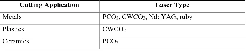
2.1 Type of laser used on metal, plastic and ceramics
(Kalpakjian and Schmid, 2006) 6
2.2 Laser cutting parameters (Yilbas, 1994) 14
3.1 Chemical composition 23
3.2 Density 23
3.3 Mechanical Properties 23
3.4 Thermal Properties 24
3.5 Machine Specification 25
3.6 Parameters for the 4 samples 26
3.7 Mounting Compound 32
3.8 Size range for ANSI/CAMI graded paper 34
3.9 Microetching etchant and procedure (ASTM E407 – 99) 36
3.10 Macroetchant etchant and procedure (ASTM E340 – 00) 38
4.2 Roughness test results 46
LIST OF FIGURES
2.1 Gas assists in laser cutting (Radovanic and Dasic, 2006). 9
2.2 Cutting rates for CO2 Laser. 12
2.3 Surface roughness in dependence on sheet thickness
(Radovanic and Dasic, 2006). 13
2.4 Experiment set up (Yilbas, 1994). 14
2.5 Spiral cut (Yilbas, 1994). 15
2.6 Picture and profile of laser cut (Radovanic and Dasic, 2006). 18
2.7 Laser cut surface (Radovanic and Dasic, 2006). 18
2.8 Cross section cut at low speed 2 cm/s, O2 gas pressure 140 kPa
(Yilbas, 1994). 20
2.9 Cross section cut at moderate speed 4 cm/s, O2 gas pressure 140 kPa
(Yilbas, 1994). 20
2.10 Cross section cut at high speed 6 cm/s, O2 gas pressure 140 kPa
(Yilbas, 1994). 20
3.1 Flow chart of experiment. 24
3.2 Laser cutting machine. 26
3.3 Roughness tester. 28
3.4 Method of designing location of area shown in photomicrograph.
(ASTM E3 – 01, 2007). 30
3.6 Grinding machine 34
3.7 Polishing machine 35
3.8 Aluminium Oxide Powder 35
3.9 Flow chart for surface modification study 40
3.10 Normal incident light being reflected by three etched surface grains
by having different orientation each. (Callister, 2005). 42
3.11 Surface structure which might appear when view with microscope; luster or texture of each grain depends on reflectance properties.
(Callister, 2005). 42
3.12 Section of grain boundary and the surface groove produce when etching.
(Callister, 2005). 42
3.13 Photomicrograph of polycrystalline specimen. (Callister, 2005). 43
4.1 Surface roughness graph. 46
4.2 Laser beam melts and vaporized material, creating a kerf.
(Laser cutting guide for manufacturing, 2003). 48
4.3 Surface of sample S1 after Laser cut. 48
4.4 Surface of sample S2 after Laser cut. 48
4.5 Surface of sample S3 after Laser cut. 49
4.11 Microstructure of sample G etches with 2% Nital. 50X magnification. 55
4.12 Iron-carbon phase diagram.
(ASM Handbook Volume 9 Metallography and Microstructure) 56
4.13 Microstructure of sample S1 etches with 2% Nital. 100X magnification. 57
4.14 Microstructure of sample S1 etches with 2% Nital. 200X magnification. 57
4.15 Microstructure of sample S2 etches with 2% Nital. 100X magnification. 58
4.16 Microstructure of sample S2 etches with 2% Nital. 200X magnification. 58
4.17 Microstructure of sample S3 etches with 2% Nital. 100X magnification. 59
4.18 Microstructure of sample S3 etches with 2% Nital. 200X magnification. 59
4.19 Microstructure of sample G etches with 2% Nital. 100X magnification. 60
4.20 Microstructure of sample G etches with 2% Nital. 200X magnification. 60
4.21 Microstructure of sample S1 etches with 2% Nital. 500X Magnification. 61
4.22 Microstructure of sample S2 etches with 2% Nital. 500X Magnification. 61
4.23 Microstructure of sample S3 etches with 2% Nital. 500X Magnification. 62
4.24 Microstructure of sample G etches with 2% Nital. 500X Magnification. 62
A Surface roughness result of sample S1 and S2.
LIST OF ABREVIATIONS
AC - Alternative current
CNC - Computer numerical control
CW - Continuous Wave
DC - Direct current
EDM - Electrical discharge machining
HAZ - Heat affected zone
LBM - Laser beam machining
LGAC - Laser generated air contaminant
OEM - Original Equipment Manufacturer
SEM - Scanning electron microscope
TEM - Transmission Electron Microscope
UV - Ultra-Violet
CHAPTER 1
In the world of today, metal working operation is a common process to human being,
but the requirements for high accuracy and precision going higher and higher each
day to enable new possible product is being produce with various kind of geometrical
shape. As the manufacturing tends to become more and more complex, more
technology will be invented and implemented. If there is possibility human tends to
produce machining operation which will not need additional machining process in
order to give a better finishing. The reason behind is to have lower cost in the
production, fewer machining operation or finishing operation will reduce the cost of
product being manufactured. Sometimes there are some circumstances which cause
the manufacturing process to be increase, such as the complexity where one
machining process cannot do all the profile or maybe there is needed to have tools
change whenever removing material of different profile. There are also additional of
time when there is a need of changing tool or even changing of machining processes
which also means change of workstation. When this happens, lead time to the next
process will be increases. Non-traditional machining process created is not only to
fulfilled the reason on increasing performance of certain manufacturing process but
the workpiece especially when heat generated which there is a high possibility
altering the properties of the material which it used to be. On the second though
material nowadays required on better quality with high hardness, toughness and
impact resistance leads to an increasing of difficulty in cutting this type of material.
But still there is a need on new material being created, which is to suits the current
manufacturing work. Conventional machined unable to cut any material which is
harder than its cutting tool but with existents of modern machining is used such as
electrolytic grinding, supersonic machining, electrical discharging machining (EDM)
and laser cutting have been discover. Laser cutting can produce a very precise and
fine surface but laser cutting do have some differences where laser cutting need to
deburring after the cutting process depends on the surface at the bottom surface will
have melted material cools at the bottom edge. Laser cutting is effective for single
piece, one-of-a-kind operation but also in mass production.
As for this project, the need is to determine any modification occur on a low carbon
steel plate is after going through laser cutting process. As we know that laser cutting
process can be very high precision and accuracy but how far will laser cutting can
bring a machining process to serve its main purpose. The reason for this research is
to determine the change on the cut surface after machining. The equipment which
will be used one will be CO2 Laser Beam Cutting machine (LVD HELIUS 2513) for
plate cutting, Surface roughness tester (Mitutoyo SJ-301) for measuring the surface
roughness, optical microscope (ZEISS Axioskop 2) and others supporting equipment
to assist in the research. Laser cutting machine will be run in optimum preloaded
parameters for the 6mm thick low carbon steel plate material where the parameter is
given by the manufacturer of the machine which ensures that the laser beam can
penetrate the plate to cut. Cut surface of the plate will be examined for its roughness
1.2 Problems Statement
Laser cutting is non contact machining process, but there is still heat generated out
during the process of cutting material. This mean during machining process, heat
generated will affect structure on the cut surface. Heat generated is very high thus it
must leads to melting of material in order to cut. Cutting gas and assists gas which is
introduced during the cutting process changes in the structure of the material and
there might cause stress in the material as it also do some cooling work. Heat
generated during machining will be cool by gas assist where it directly blown on the
molten material to enable cutting process to be run smoothly. But when there is some
situation where rapid cooling occurs therefore surface of the material being cut might
change, in this experiment the surface modification generated during the machining
process of laser cutting will be study. The changes or the formation of the layer of
different microstructure from the parents’ material will be observed. The reasons on formation of different structure and the effects on the material is examined and
1.3 Objectives
The main objectives of this study are as below:
(a) To study the cut surface of low carbon steel after laser cut.
(b) To identify any microstructure changes after machining process.
(c) To study the effect of cutting parameter on surface modification.
1.4 Scope
This research will be carried out within the limitation;
(a) Laser cutting machining used is the CO2 gas assist laser machine at FASA B
to cut the sample of material low carbon steel plate.
(b) Parameters used will be the parameters given from the machine manufacturer
for material 6mm low carbon steel plate.
(c) Numbers of samples which will be prepared will be 4 samples for laser
cutting process. Each sample will be cut using 4 different types of settings for
6mm low carbon steel plate which are the rapid, medium, slow and general
settings.
(d) Microstructure observation will be at the cross-section of the machining
1.5 Significant of Study
The significant of study in this research are:
(a) Performance of the CO2 laser cutting will be tested by how the surface
produced by observing on how parameters affect the possibility of the surface
produced.
(b) To find out the formation of the heat affected zone on laser cutting surface
and how it was form by different parameter settings during machining. How
far the heat spread from the cutting surface controlled by the parameter used
in the machining process.
(c) To find out the surface modification by laser cutting process by observing the
CHAPTER 2
LITERATURE REVIEW
This chapter will discuss about the machine which will be going to be used and also
the experiment which have been done before related to the machine which will be
going to be used. The experiment which will be closely giving hints on how the
experiment will be carried out and what is the precautions will be undertaken.
1.6 Introduction to Laser Beam Machining
Laser-beam machining (LBM) or laser cutting is a machining process using laser
(light amplification by stimulated emission of radiation) as its source. This optical
energy highly focuses on the surface of the workpiece, where this high-density
energy source melts and evaporates portions of the workpiece in a controlled manner.
Laser-beam machining does not require vacuum condition in order to operate and it
is able to machine variety of metallic and non-metallic materials. In laser beam
machining the physical parameters which is very important are the reflectivity and
thermal conductivity of the workpiece surface and its specific heat and latent heats of
melting and evaporation. The general types of laser are that has been used on metal,
Laser Beam Machining is a non-traditional machining process where the way it
absorption coefficient, thermal conductivity, specific heat and heat of vaporization of
the workpiece. (ASM Volume 16 Machining)
2.1.1 CO2 Laser Cutting
CO2 laser cutting is a cutting process using light 10.6 um (far infrared range)
wavelength, where this source of energy beam is transmitted and focused on the
surface of the material being cut by a lens. The focused laser beam heats the surface
and melting of a capillary is form throughout the depth of the material. The size of
the capillary is usually larger than the focused laser beam diameter. Gas assisting
CO2 laser cutting will enable molten material is ejected from the base of the capillary
by a jet of gas coaxial with the laser beam. Depending on what type of material being
cut, some can be cut easily with CO2 gas assisting. The cut is generated by the
movement of the focused laser beam across the surface of the material which is place
stationary or vice versa. There are also some laser cutting machine will have both
laser beam and workpiece move together to have a better complex linear cut or two
dimensional parts can be produced. CO2 laser beam energy is transmitted guided by
mirrors. The cut material will be expelled using gas jet. The distance between nozzle
and material surface will be approximately 0.2‖ + 0.004‖. The laser source usually located inside the machine and the workpiece table sizes will be in the range of 8ft x
4ft to 20ft x 6.5ft. The laser machine output power will be in the range of 1500 to
2600 Watts.
The CO2 laser will available in 2 designs, one is the axial-flow laser and another one
slow flow where the fast axial-flow will achieve 600 W/m (180 W/ft) of tube length
and have an average power up to 5000 W. Whereas the slow axial-flow laser will be
limited to 100 W/m (30 W/ft) of tube length and have less than 1500 W of output
power. Axial-flow CO2 laser can operate in either CW or pulsed mode. Pulse
frequencies in the range of 1 to 10 000 pulses per second. The transverse-flow laser
on have CW mode even its beam can be modulated with a beam chopper.
Transverse-flow laser is used when compact medium-power lasers are needed or
high powers are required where the average output power range around 2500 to 15
000 W.
CO2 laser is used in several types of application not just in cutting but also used in
drilling, engraving, ablation, structuring and welding. Nearly everything can be cut
by laser cutting process which includes all types of metal except for high reflective
index metal, all plastics, glass and wood. Material thickness in which laser cutting
will be optimized will be around 0.12‖ to 0.4‖ depends of what type of material.
Laser cutting is commonly used in cutting flat sheet steel of medium thickness for
sheet metal processing. Minimum slit size will be around 0.006‖ depending on the cutting speed. In every laser cutting the surface finish will show a striated structure.
Burring will occur on the cut surface and there will be structural changing,
deformation and tempering after laser cutting. There is also a weakness when laser
cutting thin workpiece where the gas pressure will cause the distance between the
workpiece and the nozzle hard to maintain. (ASM Volume 16 Machining)
In every machining operation there is safety consideration while handling it. In laser
cutting, safety glasses are not necessary required as there will guard shield install in
the machine as well. CO2 laser are class 4 laser therefore during the machining
process the machine is built to prevent human access to the laser beams during
machine sometimes will not be necessary as the waste produce mainly in the form of
dust therefore vacuum or filtering will be use to clean up the machine.
Laser technology is still a very young technology and it has not reached the age of 40
years. Laser is regarded as a device for producing finely controllable energy beam
which in contact with the material or the workpiece, generates considerable heat. The
laser beam enables tool-free machining where this light absorbed by the workpiece
and transform into thermal energy. Laser beam has a lot of usage and becoming one
of the important tools for cutting, welding or heat treatment. Laser cutting is
normally used in thin sheet cutting especially to use on mild steel sheet metal. Laser
cutting is very well known in cutting steel sheet material and have been apply widely
in the industrial lasers. Laser cutting is being described as thermal, noncontact,
mechanized process capable of cutting most materials with a high degree of precision
and accuracy. In laser cutting, the area where to be melted or vaporized is very small
and very well defined therefore only the surface of the material is affected by the
heating, melting and evaporation.
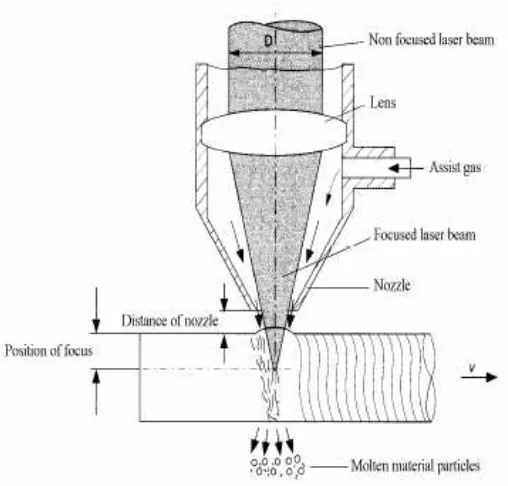
Figure 2.1: Gas assists in laser cutting (Radovanic and Dasic, 2006)
The important physical parameters in LBM are the reflectivity and thermal
conductivity of the workpiece surface and its specific heat and latent heats of melting