An Energy Management of Light Electric Vehicle
Farid Arafat Azidin
a,b, Mahammad Abdul Hannan
a* and Azah Mohamed
aa
Depart. of Electrical, Electronic and System Engineering, Universiti Kebangsaan Malaysia, 43600 Bangi, Selangor, Malaysia b
FKEKK, Universiti Teknikal Malaysia Melaka, Hang Tuah Jaya, 76109, Durian Tunggal, Melaka, Malaysia
Abstract
Oil depletion, global warming and CO2 gas emissions have become a concern and have motivated the development of
an efficient and extendable energy management system (EMS) using renewable energy sources for light vehicles. In this paper, a state-based logic control algorithm is developed for a multi-source EMS for light electric vehicle, i.e., electric scooters. The multiple sources of energy, such as a battery, fuel cell (FC), and super-capacitor (SC), EMS and power controller are designed and modeled using MATLAB. The developed control strategies continuously support the EMS of the multiple sources of energy for a scooter under normal load conditions. The performance of the proposed system is analyzed and compared with that of the ECE-47 test drive cycle in terms of vehicle speed and load power. The results show that the designed vehicle’s speed and load power closely match those of the ECE-47 test driving cycle under normal conditions. This study results suggest that the proposed control algorithm provides an efficient and feasible EMS for light electric vehicles.
Keywords: Fuel cell, battery, supercapacitors, control state, energy management system
1.Introduction
In many Asian countries, scooters and three-wheeled vehicles are notably popular and are a cheaper form of transportation. They are often used in the cities to travel short distances and avoid traffic jams. These vehicles have a capacity of 2-5 kW from an internal combustion engine (ICE). Recently, due to consumers’ concern for the environment, small HEVs have been introduced with a power system and no longer use an ICE. Lukic et al. [1] and Mulhall et al. [2] have successfully performed a correlation analysis of the three-wheeled rickshaw drive train with a hybrid configuration. A plug-in electric rickshaw with solar assistance increased the average daily range of the vehicle, if the appropriate control system was applied. Fernandez et al. [3] introduced modeling and control of a FC-battery powered hybrid system for a tramway. The study focused on an EMS in which a control strategy is developed to provide tramway load demand or to optimize the system’s energy.
Jarushi and Schofield [4] reported a combination of a battery and an SC in the multiple energy system that showed better regulation of vehicle traction compared to a battery, i.e., a single power source. The model consists of two ZEBRA batteries and an SC as the energy sources. In the EMS, the SC has two functions: to enhance the power and to extend the battery life by compensating for the high current of the load. The control strategy of the power management system followed three principles: the demand current at high acceleration, the battery current at the recommended rate and the remaining current supported by the SC. The models of the vehicle with two ZEBRA batteries have the same mass as an SC bank and a DC/DC converter. These vehicle models are simulated with standard urban driving cycles and out-of-city driving and motorways, as well. The developed control strategy saves vehicle fuel consumption and manages energy efficiently.
* Manuscript received July 12, 2012; revised August 17, 2012.
Energy Management System (EMS) SC
FC
Battery
Feedback Control System
Motor Drive DC Machine
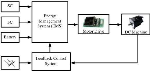
In this three-wheel light electric vehicle (LEV) system, a battery is used as the primary source of energy, while the SC is used as the auxiliary energy source, and the FC is used as an extended energy source for a high demand load. The LEV tends to use the battery as the primary energy source, to use the SC minimally and to avoid the use of the FC as an energy resource unless the demand is high. This concept is ideal for an LEV because the battery can be charged at home, and the vehicle can also make use of solar harvesting [5]. An advanced control algorithm is developed to control the switching of the battery as the main source, the SC as the auxiliary source and the FC if needed. Thus, the EMS plays an important role: it either enhances the storage capacity or changes the energy sources, as required.
The closed-loop driving system for the EMS of a three-wheel LEV is shown in Fig. 1. Multi-power sources are attached to the EMS to best selection of energy source before linked to the motor drive. In the EMS, these power sources are controlled by switches which the control system is based on the control algorithm. The system control strategy counts on the pedal acceleration which measured current energy, battery capacity and a continuous high speed energy constraint. The design concept of the energy source models, EMS, control algorithm and simulation models are briefly explained in the following sections.
Fig. 1. Multiple power sources in a closed loop motor drive system for a three-wheel LEV.
2.Energy Source Models
There are three sources of energy used in the three-wheel LEV systems: batteries, SCs and FCs.
2.1.Battery model
A simple model for battery system is designed as the objective of the research is to investigate the smoothness of the EMS. Beside, the battery model is designed near to product in the market. The battery system has been derived from SimPowerSystems and the equivalent circuit of the battery model can be expressed as [6]
( . ) 0
B it
Q
E
E
K
Ae
Q it
−
=
−
+
−
(1)where E is the constant load voltage, E0 is the no load voltage, K is the polarized voltage constant, Q is
the battery capacity, A is the exponential voltage and B is the exponential capacity of the battery. The load current i and time in second t is parameterized respectively [7].
The load current has an inversely linear relationship to the SOC value. The discharge rate is calculated [8] as follows:
1.05
100 1
Q
SOC
i
⎛
⎞
=
⎜
−
⎟
∫
⎝
⎠
(2)2.2.Fuel cell model
separated by the inner membrane. The combination of hydrogen and air caused a chemical reaction that produced energy, i.e., voltage [9]. The byproduct of the chemical reaction is hot water. A single cell voltage produced by FC according to the Nernst’s instantaneous voltage is given by [10]
2 2
where E0 is the standard potential of the hydrogen/oxygen reaction (about 1.229 V) [9], R is the universal
gas constant, F is Faraday’s constant, T is absolute temperature and
2
H
P ,
2
H O
P are partial pressure water and oxygen at the cathode.
A simple model of FC is acquired from literature review since the focus of this work is in EMS and motor drive system. The FC model is designed from a model MATLAB/SIMULINK [6]. A 6 kW, 45 V dc PEMFC was considered for the simulation.
The potential voltage E produced by the fuel cell is defined as [6]
)
fuel cell current, and ln is natural logarithm.
2.3.Super-capacitor model
The SC energy storage system act to support the battery or FC when there is a short and instant high power demand. The modeling of SC is related to the fundamental discharging circuit of the capacitor voltage dealing with the resistor and capacitor of the RC circuit. The effective discharging voltage is calculated by multiplying the initial voltage of the capacitor and the exponential of RC time constant, which is described as follows [11]-[12]:
( )
The energy produces from the SC is linearly proportional to the capacitance and voltage changes during discharge and is defined as [13]
2 2
3.1.Control algorithm
The control algorithm is designed to fulfill the condition based on the situation and to maximize energy conservation. The operational control strategies are based on the seven operation states. The major task of the system is to select the suitable power source to drive the DC motor. The control system is intelligent enough to recognize when to trigger the appropriate state. The controller determines three basic operational input conditions: pedal offset (PO) and power duration load (PD) are determined by measuring motor speed over a long period of time, and battery capacity (BC) is also determined. Based on the source conditions, the seven operational states are as follows:
State 1. (Input: Off operation): Regenerative Braking.
State 2. (Input: BC+/PD+/PO): Battery is fully used to drive the motor if there is no high power demand. Part of the energy is conserved; the FC stays not in operation and will be active when the battery charge is low.
State 3. (Input: /BC+/PD+/PO): FC takes over to drive the vehicle and charge the battery until it turns to state 2.
State 4. (Input: BC+PD+/PO): The consequence of a high power demand forces the system to activate the FC and battery as the auxiliary energy source.
State 5. (Input: BC+/PD+PO): In this situation, the battery-powered vehicle accelerates with the support of the SC. The vehicle then turns to state 2 after all energy in the SC is used.
State 6. (Input: /BC+/PD+PO): The battery is critical. The FC-powered vehicle accelerates with additional energy from the SC. After the SC tank is empty, the system changes to state 3.
State 7. (Input: BC+PD+PO): As the vehicle moves into high speed and requires acceleration, the system is forced to activate all of its energy sources.
3.2.Power control system
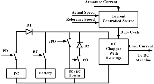
All energy sources are linked to the multi-switches. Switch activation depends on the input from pedal acceleration, battery capacity and high power demand load. The detailed system that controls the switches and the current for the vehicle power load is shown in Fig. 2.
Fig. 2. Power control system for a three-wheeled LEV
3.3.Feedback control system
The feedback control system regulates the vehicle system to follow the control strategy in the EMS. Two feedback measurements, the SOC of the battery and the vehicle speed, are used to calculate the demand of the system. Because the battery is the main source, the battery capacity is used until it reaches 50% of the SOC. Once the battery SOC is detected, it sends the signal to activate the FC. The pedal acceleration signal is evaluated by comparing the offset, which triggers the SC, if necessary.
Battery
FC SC / DC Booster
DC Chopper
With H-Bridge
Current Controlled Source
`
PD BC
/PO
PO Actual Speed Reference Speed
Armature Current
Duty Cycle
Load Current
To DC Machine D1
4.Result and Discussion
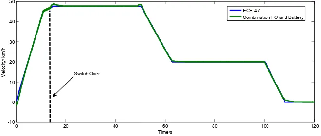
The performance evaluations for the EMS of the LEV, i.e., three-wheeled scooters, are investigated in terms of the vehicle speed, power load and multiple source loading conditions. The performance of the developed system is compared with that of the ECE-47 drive cycle to validate the proposed model. The ECE-47 drive cycle is suitable and commonly used for the performance and emissions testing of mopeds and electric scooters. The results of the vehicle speed and the ECE-47 test drive cycle in the Fig. 3 are closely matched together. The speed of the DC motor is controlled by PI-regulator. Any sudden changing speed, slightly dampening response of vehicle speed is seen in the Fig. 3. At the start, a combination of FC and battery are active, until the switch over FC lasts 15s. There is no sign of reduce speed of the vehicle system. According to the control strategy, the system starts in state 4 and then switches to state 3 after switch over.
Fig. 3. ECE-47 test cycle through a combination battery and FC for 15s then switch to FC
Fig. 4 shows a comparison between the electrical power, Pelect and the vehicle load power, Pveh. As the
vehicle starts to accelerate over 18 s, the average power demand from the DC motor is 3.3 kW. Next, the electrical power levels decrease slightly, i.e., Pveh > Pelect, because the motor torque and speed of the
vehicle gain inertia. The PI regulator attempts to minimize the use of power to follow the driving cycle because the vehicle is gaining inertia torque and speed. However, when the vehicle no longer accelerates,
Pelect and Pveh remain at 1.8 kW. A changeover of the vehicle speed causes a dampening response in the
Pelect, while the motor driving system uses the PI regulator to control vehicle speed. As the vehicle losses
speed, a regenerative power of 1.2kW is delivered and can be stored to energy storage. It takes less than 5 seconds to make the system stabilize with an electrical power of 1.4 kW when the vehicle stops decelerating and retains its speed. A generated electrical power of 0.95 kW occurred when the vehicle decelerates again. Regenerative energy that can be stored through this drive cycle is about 22 kJ.
Fig. 4. Electrical power, Pelect and mechanical power, Pmech (Pveh).
5.Conclusion
In this paper, an overview of different energy source models and a new control state-based EMS is introduced for light electric vehicles for next-generation transportation. The logic sequences of the vehicle EMS under the operating control strategy directly influences the energy harvesting of the light electric vehicle from the three renewable sources. The main function of the developed control strategies is to support the EMS of the battery, FC, and SC under normal conditions, as the primary, secondary respectively. The optimal use of the EMS is a trade-off between fuel saving with pure electric driving and motor-assistance and the battery charging cost, which counterbalances the use of electric energy. The EMS of the light electric vehicle is evaluated, analyzed and compared with the ECE-47 test drive cycle in terms of vehicle speed and load power to derive maximum efficiency from the multi-energy sources. The results show that the control strategies, the designed vehicle speed and the load power are close to the ECE-47 test driving cycle under normal load conditions. Thus, the results of this study indicate that the proposed control algorithm provides an efficient and feasible EMS for light electric vehicles.
Acknowledgements
This work was supported by Universiti Kebangsaan Malaysia (UKM), Universiti Teknikal Malaysia Melaka (UTeM) and Kementerian Pengajian Tinggi Malaysia.
References
[1] Lukic SM, Mulhall P, Emadi A. Energy autonomous solar/battery auto rickshaw. Journal of Asian Electric Vehicles, 2008; 6(2):1135-1143.
[2] Mullhall P, Lukic SM, Wirasingha SG, Lee Y-J, Emadi A. Solar-assited electric auto rickshaw three-wheeler. IEEE Trans. Vehicular Technology, 2010; 59(5):2298-2307.
[3] Fernandez LM, Garcia P, Garcia CA, Jurado F. Hybrid electric system based on fuel cell and battery and integrating a single dc/dc converter for a tramway. Energy Conversion and Management, 2011; 52(5):2183-2192.
[4] Jarushi A, Schofield N. Modelling and analysis of energy source combinations for electric vehicles. World Electric Vehicle Journal, 2009; 3:1-7.
[5] Hannan MA, Azidin FA, Mohamed A. Multi-sources model and control algorithm of an energy management system for light electric vehicles. Energy Conversion and Management, 2012; 53(1):123-130.
[6] MathWorks, SimPowerSystems. MATLAB 2008.
[7] Uzunoglu M, Onar OC, Alam MS. Modeling, control and simulation of a PV/FC/UC based hybrid power generation system for stand-alone applications. Renewable Energy, 2009; 34(3): 509-520.
[8] Thounthong P, Chunkag V, Sethakul P, Davat B, Hinaje M. Comparative study of fuel-cell vehicle hybridization with battery or supercapacitor storage device. IEEE Trans. on Vehicular Technology, 2009; 58(8):3892-3904.
[9] Basu S. Recent Trends in Fuel Cell Science and Technology. New Delhi: Springer; 2007.
[10] Garcia P, Fernandez LM, Garcia CA, Jurado F. Energy management system of fuel-cell-battery hybrid tramway. IEEE Trans. on Industrial Electronics,2010; 57(12): 4013-4023.
[11] Wikipedia. Electric double-layer capacitor. [Online]. Available: http://en.wikipedia.org/wiki/Electric_double-layer_ capacitor [12] Hannan MA, Ghani ZA, Mohamed A. An enhanced inverter controller for PV applications using dSPACE platform. J.
Photoenergy, 2010; 2011:1-10.
[13] Hannan MA, Azidin FA, Mohamed A. Light vehicle energy management system using multi-power sources. Przeglad Elektrotechiczny (Electrical Review), 2012; 3:197-204.