UNIVERSITI TEKNIKAL MALAYSIA MELAKA
DEVELOPMENT OF WIRELESS VOICE ACTIVATED ROBOT
SYSTEM
This report submitted in accordance with requirement of the Universiti Teknikal Malaysia Melaka (UTeM) for the Bachelor Degree of Manufacturing Engineering
(Robotics & Automation) (Hons.)
by
MOHD AIDIL BIN OTHMAN B051110274
890421085995
DEVELOPMENT OF WIRELESS VOICE ACTIVATED
ROBOT SYSTEM
MOHD AIDIL BIN OTHMAN
B051110274
UNIVERSITI TEKNIKAL MALAYSIA MELAKA
i
ABSTRAK
ii
ABSTRACT
The purpose of this project is to develop a wireless voice activated robot system. The proposed guidance technique is a wireless mobile robot control system which employs a voice recognition system for triggering and controlling all its movements. The mobile robot responds to the voice command from its user to perform any movements functions. The wireless voice activated controller system is communicating using two wireless devices which are divided into wireless transmitter unit and wireless receiver unit. The wireless transmitter unit was a combination between a microphone, a voice recognition unit, a microcontroller unit and a wireless module; while the wireless receiver unit was a combination between another one microcontroller unit and a wireless module. By implementing the system, the users are able to operate the mobile robot by simply speak through the wireless microphone. The movement functions of the mobile robot includes forward and reverse, turn left and turn right, and stop. The user need to trained the word spoken out in order to make sure the recognition processor can recognize the spoken words. The implementations of voice recognition unit for triggering and controlling the mobile robot movement can replace the conventional navigation method. The mobile robot can perform the desired movement when responding to the voice command from its user through a microphone that reduces the need of hand activities. The voice recognition system was designed to be dependent and can be used by one user only. The results from a series of testing have concluded that the wireless voice activated controller system is a reliable method of navigation. The overall function analysis shows the performance of the controller system when navigating the mobile robot through a path line.
iii
DEDICATION
iv
ACKNOWLEDGEMENT
v
2.1 Vehicle Guidance Technology of Mobile Robot 6 2.2 Traditional Navigation of Mobile Robot 8
2.2.1 Wire Guidance 8
2.2.2 Laser Guidance 9
2.2.3 Tape Guidance 10
2.2.4 Inertial Guidance 11
2.2.5 Problem in Navigation of Mobile Robot 12 2.3 Current Navigation Method of Mobile Robot 13 2.3.1 Wi-Fi or Wireless LAN Remote Control 13
2.3.2 Bluetooth 14
2.3.3 3G 16
vi
3.3.1 Understanding the System Design and Operation 23 3.3.2 Selection of Hardware and Software 24
3.3.2.1 Microcontroller Unit 24
3.3.2.2 Voice Recognition Unit 26
3.3.2.3 Wireless Transmitter and Receiver Unit 27
3.3.2.4 Arduino IDE Software 29
3.3.2.5 X-CTU Software 29
3.3.2.6 EasyVR Commander Software 29
3.4 Development Process (Part B) 30
3.4.1 Microcontroller Unit Setup and Test 30 3.4.2 Voice Recognition Unit Setup and Test 31 3.4.3 Wireless Transmitter and Receiver Unit Setup and Test 31
3.4.4 Interface All Units 31
4.1.1 Wireless Transmitter Unit 36
vii
4.1.2 Wireless Receiver Part 39
4.1.2.1 Selected Hardware for Receiver Part 39 4.1.2.2 Circuit Design for Wireless Receiver Part 41
4.1.3 Selected Software’s 41
4.2 Development Result 43
4.2.1 Arduino UNO Microcontroller Unit Setup and Test Result 43 4.2.1.1 Using Example Code to Blinking “L” LED on 43
Arduino UNO
4.2.2 Voice Recognition Unit Setup and Test Result 47 4.2.2.1 Train EasyVR Voice Recognition Module Using 48
EasyVR Commander
4.2.3 XBee Wireless Unit Setup and Test Result 51 4.2.3.1 XBee Shield Transmitter Module 51 4.2.3.2 XBee Shield Receiver Module 59
4.2.4 Interfacing All Modules 60
4.2.4.1 Wireless Transmitter Module Assembly 61 4.2.4.2 Wireless Receiver Module Assembly 65
viii
4.5 Summary 92
CHAPTER 5: CONCLUSION & FUTURE WORK 93
5.1 Conclusion 93
5.2 Future Work 94
REFERENCES 95
ix
LIST OF TABLES
3.1 Arduino UNO features 25
4.1 Bill of material (BOM) for wireless transmitter unit 37 4.2 Bill of material (BOM) for wireless receiver part 40
4.3 Selected software’s 42
4.4 List of voice commands and its function 50 4.5 Parameter for XBee transmitter module 58 4.6 Parameter for XBee receiver module 59
4.7 Result of voice commands testing 68
4.8 Result of displacement error for “FORWARD” test 76
4.9 Result of displacement error for “REVERSE” test 77
x The dotted blue lines represent wire guides mounted in the floor.
Solid blue lines represent information relays (Lindkvist, 1985).
2.3 Rotating laser beam and reflectors determine the AGV path. 10 This new navigation technique has expanded the flexibility of AGV
(Davich T., 2010).
2.4 Front view of SmartCaddy vehicle showing the sensors 11 and floor markings (Rosandich et al., 2002).
2.5 Bridge Connection Pattern WLAN (Feng Cui et al., 2006). 14 2.6 The e-puck robot (Mondada et al., 2009). 15 2.7 System Structure (Jincun et al., 2009). 16 2.8 OTELO Mobile Robotic System (Garawi et al., 2006). 17 2.9 Structure of a standard speech or voice recognition system 18
(http://easi.cc, 2004).
2.10 Example of the RF remote control system 18 (www.projectpiles.com, 2013).
3.1 Mobile robot controller system block diagram. 21 3.2 Overall method for design and development of the controller system 22 3.3 Flowchart of design and planning process for hardware and software
of the controller system 23
3.4 Arduino UNO microcontroller unit (www.gammon.com.au, 2011) 25 3.5 EasyVR Arduino Shield (www.astanadigital.com, 2013) 26 3.6 XBee 1mW Wire Antenna - Series 1 (www.cytron.com.my, 2013) 27 3.7 XBee Shield (without module) (www.cytron.com.my, 2013) 28
3.8 Flowchart of development process 30
xi
4.1 Transmitter circuit design 39
4.2 Receiver circuit design 41
4.3 Interfacing Arduino UNO to a computer 43
4.4 Arduino IDE sketch 44
4.5 Codes examples in Arduino IDE 44
4.6 “Blink” code 45
4.7 Compiling sketch 46
4.8 Uploading sketch 47
4.9 Assembly of EasyVR and Arduino Uno 48
4.10 PC mode 48
4.16 XBee Shield mounted to Arduino UNO 53
4.17 XBee configure code 54
4.18 X-CTU test 55
4.19 Communication Success 56
4.20 Modem configuration. 57
4.21 Terminal Setup (transmitter) 58
4.22 Terminal Setup (receiver) 60
4.23 Arduino UNO for transmitter 61
4.24 Jumper wire 61
4.25 Jumper wires connected on Arduino UNO 62 4.26 EasyVR Shield mounted on Arduino UNO 62 4.27 Microphone plugged on EasyVR Shield 63 4.28 XBee module mounted on XBee Shield 63 4.29 XBee Shield connected to jumper wires 64 4.30 Complete wireless transmitter module. 64 4.31 Arduino UNO microcontroller board for receiver 65
4.32 XBee module with XBee Shield 65
xii
4.34 Mobile robot platform 69
4.35 “FORWARD” and “REVERSE” test setup 70 4.36 “FORWARD” and “REVERSE” of Test 1 71 4.37 “FORWARD” and “REVERSE” of Test 2 72
4.38 “FORWARD” and “REVERSE” Test 3 73
4.39 “FORWARD” and “REVERSE” of Test 4 74 4.40 “FORWARD” and “REVERSE” of Test 5 75 4.41 Method for measuring displacement error 76 4.42 “RIGHT” turn and “LEFT” turn of test setup 78 4.43 “RIGHT” turn and “LEFT” turn of test 1 and 2 79 4.44 “RIGHT” turn and “LEFT” turn test 3 and 4 80 4.45 “RIGHT” turn and “LEFT” turn of test 5 81 4.46 Method to measures the degree of turning 82
4.47 Navigation experiment setup 83
4.48 Navigation experiment 1 84
4.49 Navigation experiment 2 85
4.50 Navigation experiment 3 86
4.51 Navigation Experiment 4 87
4.52 Navigation Experiment 5 88
xiii
LIST OF ABBREVIATIONS, SYMBOLS AND
NOMENCLATURE
AGV - Automated Guided Vehicle
LED - Light Emitting Diode
3G - Three Generation
FM - Frequency Modulation
RF - Radio Frequency
LGV - Laser Guided Vehicle
AGC - Automated guided carts
IEEE - Institute of Electrical and Electronics Engineers
WLAN - Wireless local area network
PC - Personal computer
PDA - Personal digital assistant
OS - Operating system
MBM - Map based mode
xiv GPS - Global Positioning System
GIS - Geography Information System
IR - Infrared
RFID - Radio-frequency identification
1
This report presents the development and performance analysis of the wireless voice activated controller system for mobile robot, which is the main project proposed in this report.
1.1 Background
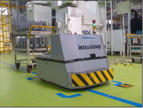
Figure 1.1: An example of mobile robot or Automated Guided Vehicle (AGV)
(www.wheelomania.com, 2013).
A mobile robot is manually or automatically controlled by programming the robot to follow wires in the floor, markers, uses vision or laser as a navigation device for the robot. They are widely used in industrial applications for transporting materials around a warehouse or a manufacturing facility.
INTRODUCTION
2
A mobile robot have many advantages compared to other types of material handling systems, including reliable, flexibility to changes in the material handling requirements, automatic operation, improved positioning accuracy, easily expandable layout and system capacity, reduced handling damage, and automated interfaces with other systems.
The first mobile robot was carried out to market in the 1950s, by Barrett Electronics of Northbrook, Illinois, where at that time it was simply a tow truck that navigating to follow a wire in the floor. The technology is now has become more sophisticated and today automated vehicles are mainly laser navigated, LGV (Laser Guided Vehicle) (Sharma M., 2012).
A mobile robot uses vehicle guidance technology to define path ways and to control it movement to follow the pathway. Based on latest technology, there are some example of guidance technology such as laser guidance system (LGVs), wire guidance, magnetic guidance, tape guidance or line follower, and etc. The example of a mobile robot is shown in Figure 1.1.
1.2 Motivation
The rapid growth of technology has introduced the voice recognition system that has been implemented in many applications. Nowadays, the voice recognition system became more popular in use as voice based remote control to control various mobile robot and home appliances.
3
Based on the problem, a new controller system which employs a voice recognition system is to be designed for triggering and controlling all the mobile robot movements. The mobile robot responds to the voice command from its user through a wireless transmission to perform any movement functions. This control system integrates a microcontroller, voice recognition processor, wireless communication unit and microphone to control the mobile robot according to the user command. The user can simply speak to the microphone to operate the mobile robot from a distance.
1.3 Problem Statement
The first problem is the use of line follower to control the mobile robot by navigating the mobile robot to follow a tape or paint strips that have a draw back where the tape or paint strips may become damaged or dirty when the mobile robot is being embedded in high traffic areas. This may affect the sensitivity of the line follower sensor to follow the line accurately and may resulting lost track. The line need to be clean or repaint frequently to maintain the mobile robot movement. With the presence of the wireless voice activated controller system, the mobile robot can be control by simply using voice command wirelessly without following any line or paint strips. The user can choose any available route to navigate the mobile robot to any location.
4
1.4 Project Objectives
To develop a wireless voice activated controller system for a mobile robot.
To analyse the performance of the wireless voice activated controller system.
1.5 Project Scopes
The basic functions of the wireless voice activated controller system for mobile robot includes, Forward and Reverse Movements, left and right turns, as well as STOP function.
The mobile robot will be controlled wirelessly through a microphone.
The voice recognition system is designed for speaker dependent (one user) applications. This means the mobile robot can be controlled by one user only. If the users change, the system need to be reprogramming based on the new users voice.
The connectivity range between transmitter and receiver of the wireless voice activated controller system will not be covered in this project.
The ability of the wireless voice activated controller system to recognize the command word even in the presence of the background noise will not be discussed in this project.
1.6 Report Structure
This report consists of five chapters.
Chapter 1 shows the introduction of mobile robot and its vehicle guidance technology, background and brief history, the problem statement of the project, project objectives and scopes.
5
Chapter 3 propose some ideas on how the project will be implemented. The chapter will lists out the steps and methods involved in each process of the project. This methodology includes the software and hardware design and explanation on overall system theory of operation for the development of the wireless voice activated controller system for the mobile robot.
Chapter 4 provides the result and analysis of data based on system evaluation. It discusses on how the data are taken in order to analyse the performance of the wireless voice activated controller system.
6
This project is focusing on the development of wireless voice activated controller system for mobile robot. Section 2.1 of this report will explain the introduction of vehicle guidance technology of mobile robot, section 2.2 will explain about traditional navigation method and problem in navigation of mobile robot; section 2.3 will explain about the current navigation method of mobile robot, section 2.4 will explain about the propose project of wireless voice recognition based remote control for mobile robot, and lastly, section 2.5 summary of this chapter.
2.1 Vehicle Guidance Technology of Mobile Robot
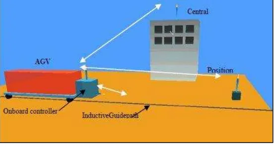
Figure 2.1: Sketch of a basic mobile robot system using fixed path guidance technology
(Kelly et al., 2011).
LITERATURE REVIEW
7
K. Anitha et al. (2013) states that Vehicle Guidance Technology (VGT) shows the path ways and guide vehicles to follow the pathway.
AGV guidance systems have been growing for about 50 years. Kelly et al. (2011) defined that there are three guidance methods that have been popular over the time. Wire guidance is one of the guidance technologies which use wires embedded in the floor that are sensed inductively to determine vehicle position with the help of the wire. This in an oldest technology that is not used much today. Other guidance technology is inertial guidance that uses gyroscope and wheel odometer (measurement of distance travelled). This navigation technique is used to implement very accurate dead reckoning. Magnets are placed in the floor at regular intervals to be used to reset the unavoidable drift of the dead reckoning system. Laser guidance is the latest guidance technology that uses a spinning laser emitter- receiver that is mounted on the vehicle. It sense the bearings to retro reflective landmarks placed accurately in the facility and then it triangulates an accurate solution. Examples of fixed path guidance technology include rail tracks, embedded wires or other type of guide-ways (see Figure 2.1).
Today modern AGV systems do not use fixed guide-paths. The guide-paths may be computer-programmed and transferred to the vehicle’s controllers. These vehicles are free-ranging and can find their path using optical (laser), magnetic, odometer, gyroscope, vision, or radio- frequency techniques (Tompskins et al., 2003).
An issue problem in the guide-path design is selecting a suitable type of guide-path system, but a guideline to select an appropriate guide-path system is not available yet. The conventional guide-path system can be seen regularly in warehouses and distribution centres (Koster et al., 2004).
8
2.2 Traditional Navigation of Mobile Robot
The guidance technique can be selected based on the type of mobile robot selected, its application, requirement and environmental limitation. Some of the significant guidance techniques include:
2.2.1 Wire Guidance
In wire navigation, a wired sensor is placed on the bottom of the AGV by facing to the ground. Then, a slot is cut in the ground approximately about 1 inch below the ground to place an energized wire. A radio frequency will be transmitted from the rooted wire and allows the sensor to detect the wire and then follows the path. This guidance technique is an earlier technology which is not used much today (Kelly et al., 2011).
Davich T. (2010), states that the key to an AGV lies within the guidance system. Methods in tracks or floor markings, such as painted lines or glued on reflective tape, can be used as a guidance system for AGV. The method that cause permanent track is not desirable and continuous wear on markings can cause system reliability issues.