Faculty of Mechanical Engineering
MODELING SOUND ABSORPTION OF MICRO-PERFORATED
PANEL USING WAVE PROPAGATION METHOD
Muhammad Sajidin Py
Master of Science in Mechanical Engineering
MODELING SOUND ABSORPTION OF MICRO-PERFORATED PANEL USING WAVE PROPAGATION METHOD
MUHAMMAD SAJIDIN PY
A thesis submitted
in fulfillment of the requirements for the degree of Master of Science in Mechanical Engineering
Faculty of Mechanical Engineering
DECLARATION
I declare that this thesis entitled ”Modeling Sound Absorption of Micro-perforated Panel
Using Wave Propagation Method” is the result of my own research except as cited in the
ref-erences. The thesis has not been accepted for any degree and is not concurrently submitted
in candidature of any other degree.
Signature : ...
Name : ...
APPROVAL
I hereby declare that I have read this thesis and in my opinion this thesis is sufficient in terms
of scope and quality for the award of Master of Science in Mechanical Engineering
Signature : ...
Supervisor Name : ...
DEDICATION
ABSTRACT
A micro-perforated panel (MPP) absorber has been known widely as an alternative absorber
to the conventional fibrous type acoustic material. The MPP system is arranged with
dis-tance from a rigid wall to provide an air gap layer. Several theoretical approaches to predict
the sound absorption of the MPP have been published. In particular for the double MPPs,
approximate expression for the air gap impedance is used which yields deviation in the
re-sult when it is compared with the experiment. In this study, wave propagation technique is
proposed to represent the behaviour of sound incident and reflected in the MPP system. The
motion of the MPP is also included in the model. The proposed models provide an attractive
technique to predict the sound absorption as well as the transmission and reflection. The
MPP can be set to be a solid panel by adjusting the impedance of the holes to infinity and
the solid panel can be turned into a rigid wall by setting the panel impedance to infinity.
The model can be applied for the single MPP and multi-layer MPPs; a stand-alone system
without rigid wall as well as the system backed with a rigid wall. The results for the MPP
system backed by a rigid wall then is compared with experimental data. It is found that the
result from the wave propagation technique has a better good agreement with the experiment
ABSTRAK
Penyerap panel bertebuk mikro (MPP) telah dikenali secara meluas sebagai sistem
peny-erap suara alternatif kepada bahan akustik konvensional dari jenis serat. Sistem MPP
dis-usun pada jarak tertentu dari dinding untuk menghasilkan lapisan ruang udara. Beberapa
pendekatan secara teori untuk meramalkan penyerapan bunyi bagi MPP telah diterbitkan.
Persamaan anggaran untuk impedans ruang udara digunakan, khususnya bagi dua lapisan
MPP yang menghasilkan sisihan di antara teori dan eksperimen. Dalam kajian ini, teknik
perambatan gelombang dicadangkan bagi menerangkan tingkah laku bunyi langsung dan
pantulan bunyi dalam sistem MPP. Pergerakan MPP juga disertakan ke dalam model. Model
yang dicadangkan menyediakan satu teknik yang menarik untuk meramalkan penyerapan
bunyi serta penghantaran dan pantulan. MPP juga boleh disesuaikan menjadi panel yang
kukuh dengan mengubah suai impedans pada lubang sehingga menjadi tak terhingga dan
panel yang kukuh ini boleh ditukar menjadi dinding pegun dengan menetapkan impedans
panel juga kepada nilai tak terhingga. Model ini boleh diaplikasi bagi sistem MPP tunggal
dan sistem MPP banyak lapisan; sistem yang berdiri sendiri samada dengan atau tanpa
dinding pegun. Hasil untuk MPP dengan dinding pegun kemudian dibandingkan kepada
data eksperimen. Didapati bahawa model perambatan gelombang mencapai persetujuan
ACKNOWLEDGEMENTS
In the name of Allah, The Beneficient, The Merciful
Alhamdulillah, I would like to thank Allah the Almighty for His blessing and mercy. My
sincere gratitude goes to my supervisor, Dr. Azma Putra for his supervision, support and
encouragement towards the completion of this thesis. Also for the late Pn. Nor Liana binti
Salleh for her assistance in this project. I would like to acknowledge the Ministry of Higher
Education Malaysia (MoHE) for the financial support under the Fundamental Research Grant
Scheme (FRGS).
My gratitude is also adressed to my beloved parents, Mustafa Kamal and Murni Mizan for
their love and pray for me. To my brothers and sisters, Musnizar Safari, Ali Iqbal Py, Hawa
Thayyibah Py, and Muhammad Tanzil Khair Py for their support.
I would like to thank all my colleagues in the ’acoustics and vibration’ group for the
friend-ship, support and the brilliant discussion until completion of this thesis. Also thanks to PPI
UTeM, lecturer, staff and technicians in UTeM who help me directly or indirectly throughout
TABLE OF CONTENTS
1.3 Type of sound absorbers 2
1.3.1 Porous absorber 3
1.3.2 Helmholtz resonator 4
1.3.3 Panel absorber 6
1.4 Sustainable and green absorbers 7
1.4.1 Natural fibers as acoustic materials 7 1.4.2 Micro-perforated panel as sound absorber 9
1.5 Objectives 13
1.6 Scope of the study 13
1.7 Methodology 13
1.9 Thesis contributions 16
1.10 Summary 17
2 INTRODUCTION TO WAVE PROPAGATION TECHNIQUE 18
2.1 Introduction 18
2.2 Reflection and transmission of sound waves 18 2.2.1 Wave transmission from one fluid to another 20 2.2.2 Wave transmission through a fluid layer 23 2.2.3 Wave transmission through a solid surface 27
2.3 Summary 29
3 WAVE PROPAGATION TECHNIQUE TO MODEL SOUND ABSORPTION
FOR MICRO-PERFORATED PANEL 31
3.1 Introduction 31
3.2 Hole impedance and mean particle velocity 31 3.3 Absorption coefficient of a single micro-perforated panel (MPP) 36
3.4 Double micro-perforated panel (DMPP) 44
3.4.1 Absorption coefficient of DMPP 44
3.5 Micro-perforated panel with solid panel 54 3.5.1 Absorption coefficient of a MPP backed by solid panel 54 3.5.2 Absorption coefficient of a MPP backed by a rigid surface 59 3.5.3 Absorption coefficient of DMPP backed by a solid panel 62 3.6 Electro-acoustical equivalent circuit 69
3.6.1 Summary 75
4 EXPERIMENTAL VALIDATION 76
4.1 Introduction 76
4.2 Samples of micro-perforated panels and experimental setup 76 4.3 Validation for single micro-perforated panel 79 4.4 Validation for double micro-perforated panel (DMPP) 82
4.5 Summary 87
5 CONCLUSION AND RECOMMENDATIONS FOR FUTURE RESEARCH 88
5.1 Introduction 88
5.2 Conclusion 88
LIST OF TABLES
TABLE TITLE PAGE
LIST OF FIGURES
FIGURE TITLE PAGE
1.1 Comparison of global warming potential of conventional and natural
mate-rials (Asdrubali, 2006). 2
1.2 Type of porous sound absorbing materials (Arenas and Crocker, 2013). 3
1.3 Diagram of a Helmholtz resonator. 4
1.4 Application of Helmholtz resonator : (a) in home theater (Sensibleaudio, 2009) and (b) in Queen Elizabeth Hall (Barron, 2010). 5 1.5 Construction of panel absorber mounted on rigid wall. 6 1.6 Application of panel absorbers mounted at wall (WSDG, 2014). 7 1.7 Natural fibers materials : (a) coir fiber sheet (Fouladiet. al., 2011) and (b)
sugar cane fiber (Putraet. al., 2013a). 8 1.8 Applications of MPP in buildings: (a) the Deutsches Historisches Museum,
Berlin and (b) studio RTL, Koln (Fuchs and Zha, 2006). 10
1.9 The research methodology flow chart. 15
2.1 Sound waves on a boundary between medium with different characteristic
acoustic impedances. 21
2.2 The propagation of wave in three-layer media. 24 2.3 The power coefficient of reflection (black line) and transmission (blue line)
—z2 = 10z1,− − z2 = 20z1,· · · z2 = 30z1,− · − · z2 = 40z1. 26 2.4 The behaviour of sound energy through medium : (a) some of energy are
transmitted and absorbed,Γ = Γt+ Λ(b) fully transmitted,Γ = Γtand (c)
fully absorbed,Γ = Λ. 29
3.1 Schematic diagram of particle velocity around a perforated panel. 32 3.2 Schematic diagram of a perforated panel (Putra, 2008). 33 3.3 Explanation of real and imaginary parts of hole impedance (Putra, 2008). 34 3.4 The real (thin line) and imaginary (thick line) part of the acoustic impedance
3.8 Power transmission coefficient of a single MPP excited by normal incident of acoustic loading (t = 1mm,σ = 1 %; —do= 0.4mm,− − do = 0.6mm,
· · · do = 0.8mm). 41
3.9 Power transmission coefficient of a single MPP excited by normal incident of acoustic loading (t= 1mm,do = 0.5mm, —σ = 0.5 %,− − σ= 1 %,
· · · σ = 1.5 %). 41
3.10 Power absorption coefficient (excluding the transmission) of a single MPP excited by normal incident of acoustic loading (t = 1 mm, σ = 1 %; —
do = 0.4mm,− − do= 0.6mm,· · · do = 0.8mm). 43
3.11 Power absorption coefficient (excluding the transmission) of a single MPP excited by normal incident of acoustic loading (t = 1mm, do = 0.5mm;
—σ = 0.5 %,− − σ = 1 %,· · · σ= 1.5 %). 43
3.12 The schematic view of double MPP without any rigid backing surface ex-cited by sound wave under normal incidence. 45 3.13 (a) Power reflection coefficient and (b) power transmission coefficient of
DMPP without any rigid backing surface for varying hole diameters (tMPP=
1 mm, l = 50 mm, σ = 1 %; — do = 0.3 mm, − − do = 0.5 mm,
− · − · do = 0.7mm,. . . do= 0.9mm). 49
3.14 (a) Power reflection coefficient and (b) power transmission coefficient of DMPP without any rigid backing surface for varying perforation ratios (tMPP = 1 mm, do = 0.5 mm, l = 50 mm; — σ1,2 = 0.5 %, − − σ1,2 = 1 %,
· · · σ1,2 = 1.5 %). 49
3.15 (a) Power reflection coefficient and (b) power transmission coefficient of DMPP without any rigid backing surface for varying air gaps (tMPP= 1mm,
do = 0.5mm,σ = 1%; —l= 10mm,− − l= 30mm,− · − · l= 50mm,
· · · l = 70mm). 50
3.16 Power absorption coefficient of DMPP without any rigid backing surface for varying hole diameters (tMPP = 1 mm, l = 50 mm, σ = 1 %; — do1,2 = 0.3mm,− − do1,2 = 0.5mm,− · − · do1,2 = 0.7mm,· · · do1,2 = 0.9mm). 52
3.17 Power absorption coefficient of DMPP without any rigid backing surface for varying perforation ratios (tMPP = 1 mm, do = 0.5mm, l = 50 mm;
— σ1,2 = 0.5 %,− − σ1,2 = 1 %,· · · σ1,2 = 1.5 %). 53
3.18 Power absorption coefficient of DMPP without any rigid backing surface for varying air gaps (tMPP = 1mm,do = 0.5mm,σ = 1%; —l1,2 = 10 mm,
− − l1,2 = 30mm,− · − · l1,2 = 50mm,· · · l1,2 = 70mm). 53 3.19 Schematic diagram of a single MPP backed by a solid panel excited by
nor-mal incidence of acoustic loading. 55
3.20 (a) Power reflection coefficient and (b) power transmission coefficient of MPP backed by a solid panel for varying hole diameters (tMPP = 1mm,l= 50mm,σ = 1%; —do = 0.3mm,− − do = 0.5mm,− · − · do = 0.7mm,
· · · do = 0.9mm). 56
3.21 (a) Power reflection coefficient and (b) power transmission coefficient of MPP backed by a solid panel for varying perforation ratios (tMPP = 1 mm,
3.22 (a) Power reflection coefficient and (b) power transmission coefficient of MPP backed by a solid panel varying air gaps (tMPP= 1mm,do = 0.5mm,
σ= 1%; —l = 10mm,− − l= 30mm,− · − · l = 50mm,· · · l= 70mm). 57 3.23 Power absorption coefficient (excluding the transmission) of a single MPP
backed by a solid panel with air gap (l = 50 mm,tMPP = 1mm, σ = 1%;
—do = 0.3mm,− − do = 0.5mm,− · − · do = 0.7mm,· · · do = 0.9mm). 58
3.24 Power absorption coefficient (excluding the transmission) of a single MPP backed by a solid panel with air gap (l = 50 mm, tMPP = 1 mm, do = 0.5mm; —σ = 0.5 %,− − σ= 1 %,· · · σ = 1.5 %). 58 3.25 Power absorption coefficient (excluding the transmission) of a single MPP
backed by a solid panel with air gap (tMPP= 1mm,do = 0.5mm,σ= 1%;
—l = 10mm,− − l= 30mm,− · − · l = 50mm,· · · l= 70mm). 59
3.26 Schematic diagram of MPP backed by a solid panel adjusted to MPP backed
by rigid surface. 60
3.27 Power transmission coefficient of MPP backed by a rigid surface (l= 50mm, tMPP = 1 mm, σ = 1 %; —do = 0.4 mm, − − do = 0.6 mm,
· · · do = 0.8mm). 61
3.28 Power transmission coefficient of MPP backed by rigid surface (l = 50 mm, tMPP = 1 mm, do = 0.5 mm; — σ = 0.5 %, − − σ = 1 %,
· · · σ = 1.5 %). 61
3.29 Power transmission coefficient of MPP backed by rigid surface (tMPP=
1 mm, do = 0.5 mm, σ = 1 %; — l = 10 mm, − − l = 30 mm,
− · − · l = 50mm,· · · l= 70mm). 62
3.30 The schematic view of double MPP backed by an air layer and a flexible panel excited by sound wave under normal incidence. 63 3.31 Sound absorption coefficient of DMPP backed by a rigid surface (l = 75mm,
(d−l) = 150mm,tMPP1,2 = 1mm, σ = 1%; —do = 0.4mm, − − do =
0.6mm,− · − · do = 0.8mm,· · ·do = 1mm). 67
3.32 Sound absorption coefficient of DMPP backed by a rigid surface (l = 75mm,
(d−l) = 150mm,tMPP = 1mm,do = 0.5mm; —σ = 0.5%,−−σ = 1%,
· · · σ = 1.5%). 68
3.33 Sound absorption coefficient of DMPP backed by a rigid surface (tMPP = 1 mm, do = 0.5 mm, σ = 1 %; — l = 20 mm with (d− l) = 80 mm, − −l = 40mm with(d−l) = 60mm,− · − · l = 60mm with(d−l) =
40mm,· · · l = 80mm with(d−l) = 20mm). 68
equiv-3.38 Absorption coefficient of MPP backed by a rigid surface; electrical circuit (black line) and wave propagation (blue line) witht = 1mm,σ = 1 %,
do = 0.4mm; —l = 10mm,− − l= 50mm. 72
3.39 Absorption coefficient of double MPP backed by a rigid surface; electrical circuit (black line) and wave propagation (blue line) witht1,2 = 1mm,l1,2 =
50mm,σ1,2 = 1 %; —do = 0.4mm,− − do = 0.8mm. 73
3.40 Absorption coefficient of double MPP backed by a rigid surface; electrical circuit (black line) and wave propagation (blue line) witht1,2 = 1mm,l1,2 =
50mm,do1,2 = 0.4mm; —σ = 0.5 %,− − σ = 1 %. 74
3.41 Absorption coefficient of double MPP backed by a rigid surface; electri-cal circuit (black line) and wave propagation (blue line) witht1,2 = 1 mm,
σ1,2 = 1 %,do1,2 = 0.4mm; —l= 10mm,− − l = 50mm. 74
4.1 (a) MPP sample withdo = 0.5 mm,σ= 1% and (b) MPP withdo = 0.5 mm,
σ= 0.5%. 77
4.2 Schematic diagram of experimental setup. 79 4.3 Validation of absorption coefficient of single MPP backed by a rigid surface
for MPP = 0.5% (· · · =experiment, −− = equivalent circuit, — =wave propagation); a)l= 10 mm, (b)l= 14 mm, (c)l= 18 mm and (d)l= 22 mm. 80 4.4 Validation of absorption coefficient of Single MPP backed by a rigid surface
for MPP = 1% (· · · = experiment, −− = equivalent circuit, — = wave propagation); a)l= 10 mm, (b)l= 14 mm, (c)l= 18 mm and (d)l= 22 mm. 81 4.5 Validation of absorption coefficient of DMPP backed by a rigid surface with
MPP1,2 = 0.5 % (· · · =experiment, −− =equivalent circuit, — = wave propagation); (a)l= 10 mm and(d−l)= 19 mm, (b)l= 20 mm and(d−l)
= 29 mm, (c)l= 30 mm and(d−l)= 39 mm. 83 4.6 Validation of absorption coefficient of DMPP backed by a rigid surface with
MPP1= 0.5 % and MPP2= 1 % (· · ·=experiment,−−=equivalent circuit, —=wave propagation); (a)l= 10 mm and(d−l)= 19 mm, (b)l= 20 mm and(d−l)= 29 mm, (c)l= 30 mm and(d−l)= 39 mm. 84 4.7 Validation of absorption coefficient of DMPP backed by a rigid surface with
MPP1= 1 % and MPP2= 0.5 % (· · ·=experiment,−−=equivalent circuit, —=wave propagation); (a)l= 10 mm and(d−l)= 19 mm, (b)l= 20 mm and(d−l)= 29 mm, (c)l= 30 mm and(d−l)= 39 mm. 85 4.8 Validation of absorption coefficient of DMPP backed by a rigid surface with
MPP1,2 = 1 % (· · · = experiment, −− = equivalent circuit, — = wave propagation); (a)l= 10 mm and(d−l)= 19 mm, (b)l= 20 mm and(d−l)
LIST OF ABBREVIATIONS
DLMPP DoubleLeafMicroPerforatedPanel Hz Hertz
ISO InternationalOrganization forStandardization ITM ImpedanceTransferMethod
kHz kiloHertz
MPP MicroPerforatedPanel NF NaturalFiber
LIST OF PHYSICAL CONSTANT
Speed of sound c = 343 m/s−1
Density of the air ρ = 1.2kgm−3
Viscosity of the air va = 1.8×10−
5
LIST OF SYMBOLS
A, B Complex amplitude of sound pressure
bo The distance between hole
do Hole diameter
f Frequency
I, Ii, Ir, It Sound Intensity
j =√−1 Imaginary unit
k Acoustic wavenumber
l MPP distance to the solid plate/MPP/Rigid wall
m Mass per unit area of the solid panel
M Mass per unit area of the MPP
pi, pr, pt, pA, pB Sound pressure
r Damping cosntant per unit area
R Sound pressure reflection coefficient
s Stiffness per unit area
s1 Separation distance between the two microphones
t Thickness of panel
T Sound pressure transmission coefficient
v Particle velocity
¯
v Average surface particle velocity
vp Velocity of the panel
Zo Hole impedance
Zo,R Hole impedance, real part
Zo,I Hole impedance, imaginary part
Ztot Total impedance
G11 Auto-spectrum
G12 Cross-spectrum
H12 Transfer function between microphone-1 and microphone-2
ω Angular frequency
σ Perforation ratio
τ Intensity transmission coefficient
γ Intensity reflection coefficient
Γ Power transmission coefficient
Ψ Power reflection coefficient
Λ Power absorbed by material
LIST OF PUBLICATIONS
Journal Articles
A. Putra, M. Sajidin Py, N. L. Salleh, Modelling the Effect of Flexural Vibration on
Sound Absorption of a Micro-Perforated Panel Using Wave Propagation Method,
Ap-plied Mechanics and Materials, Vol.471, pp. 255-260 (2014).
A Putra, A.Y. Ismail, R. Ramlan, M.R. Ayob, M. S. Py, Normal Incidence of Sound
Transmission Loss of a Double-Leaf Partition Inserted with a Microperforated Panel,
Advances in Acoustics and Vibration, Vol.2013, Article ID 216493 (2013).
Proceedings
M. Sajidin Py, A. Putra, N. Salleh, H. Efendy, Modelling the Effect of Vibration on
the Sound Absorption Performance of Green Sound Absorber using Wave Propagation
Technique. Proceedings of 3rd International Conference on Engineering and ICT
CHAPTER 1
INTRODUCTION
1.1 Introduction
This chapter introduces the background of the study and the past research works
con-cerning the sound absorbers. This is started by introducing the type of sound absorbers and
the potential of natural fibers as alternative sound absorber materials which are more
envi-ronmentally friendly. Employment of micro-perforated panel (MPP) as the newest method
of sound absorber is also presented.
1.2 Background
Good acoustic performance is important in buildings such as classrooms, health care
facilities, auditoriums and concert halls. In classrooms, the ability to hear and understand
what is being said is vital for learning. When acoustical performance in classroom is poor,
this will affect speech understanding, attention, concentration and eventually academic
achieve-ment. The characteristic of auditorium contributes greatly to the perceived sound of speech.
It is hard to understand speech when echoes are too strong. People tend to slow down their
speech, talk louder and try to pronounce words more precisely in an effort to make the
received speech intelligible. The same applies to concert halls where great acoustic
perfor-mance is important to provide an enjoyable auditory experience.
To maintain good acoustic quality in a room due to late reflections which cause the
echos and high reverberation time, the surfaces of walls or ceiling in general, are covered by
which are known to not only have negative impacts concerning their risk on pollution, health
and fire hazards, but also contribute to CO2 pollution in their fabrication that can triggers
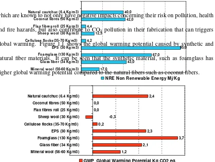
global warming. Figure 1.1 shows the global warming potential caused by synthetic and
natural fiber materials. It can be seen that the synthetic material, such as foamglass has
higher global warming potential compared to the natural fibers such as coconut fibers.
3
assessment results: Cumulated Energy Demand (CED) and Non-Renewable Energy (NRE) fraction, Global Warming Potential (GWP) and Acidification Power (AP). A comparison based on the Ecoinvent database between the environmental impacts of some traditional and natural sound insulation materials from cradle to gate is shown in Fig. 1 [4]: cellulose, flax and sheep wool have the lowest impacts on the considered categories.
17,0
GWP Global Warming Potential Kg CO2 eq.
Fig. 1. Ecoinvent. Comparison of environmental impacts of traditional and natural materials. [4]
Figure 1.1 Comparison of global warming potential of conventional and natural ma-terials (Asdrubali, 2006).
These issues have attracted attention of researchers for new absorptive materials which
are more enviromental friendly. Several studies are therefore focused in investigating natural
fibers to be employed as sound absorber. The natural fibers give more advantages than
synthetic ones as they are renewable and available in abundance amount in certain countries.
The next sections first discuss the type of sound absorbers in practice followed by the concept
panel and volume absorbers are most effective at lower frequencies.
1.3.1 Porous absorber
Porous absorbers are often used for the purpose of absorbing sound due to their ability
to absorb most of the sound energy striking them. Common examples are mineral wools,
fiberglass, open cell foams, acoustic tiles, carpets and curtains.
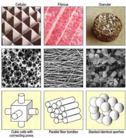
Based on their microscopic configurations, porous absorbing materials can be
classi-fied as cellular, fibrous or granular. Their main types, typical microscopic arrangements and
physical models are shown in Figure 1.2.
Figure 1.2 Type of porous sound absorbing materials (Arenas and Crocker, 2013).
When sound wave propagates in a porous absorber, the movement of air motion
in-duced by sound wave through narrow constrictions produces losses of momentum. This due
pores. This account for most significant at high frequency losses (Long, 2005). At low
fre-quencies, more significant absorption due to thermal conduction from the air to the absorber
material (Cox and D’Antonio, 2009).
1.3.2 Helmholtz resonator
Helmholtz resonator is widely used to achieve absorption at low frequency. This type
of sound absorber was invented by German physicist Hermann von Helmholtz (1821-1894).
Resembling a spring system with damping to provide absorption at the resonant frequency
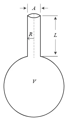
of the system. A simple Helmholtz resonator is illustrated in Figure 1.3 which consists of
an enclosed volumeV, having a small neck of areaA(opening at one end) which lengthL.
The principle is that the air in the neck acts like a fluctuating mass and the air in the cavity
acts like a spring (Vigran, 2008). The sound energy is ’consumed’ to vibrate the mass-spring
system and thus the optimum energy absorbed by resonator is at the resonant frequency.
A
L