iii
HOME APPLIANCES CONTROL USING GSM
LIEW JIA QI
This report is submitted in partial fulfillment of the requirements for the award of Bachelor of Electronic Engineering (Industrial Electronics) With Honours
Faculty of Electronic and Computer Engineering Universiti Teknikal Malaysia Melaka
iii
UNIVERSTI TEKNIKAL MALAYSIA MELAKA
FAKULTI KEJURUTERAAN ELEKTRONIK DAN KEJURUTERAAN KOMPUTER
BORANG PENGESAHAN STATUS LAPORAN PROJEK SARJANA MUDA II
Tajuk Projek : HOME APPLIANCES CONTROL USING GSM
Sesi
Pengajian : 2009/2010
Saya LIEW JIA QI
mengaku membenarkan Laporan Projek Sarjana Muda ini disimpan di Perpustakaan dengan syarat-syarat kegunaan seperti berikut:
1. Laporan adalah hakmilik Universiti Teknikal Malaysia Melaka.
2. Perpustakaan dibenarkan membuat salinan untuk tujuan pengajian sahaja.
3. Perpustakaan dibenarkan membuat salinan laporan ini sebagai bahan pertukaran antara institusi
pengajian tinggi.
4. Sila tandakan ( √ ) :
SULIT*
(Mengandungi maklumat yang berdarjah keselamatan atau kepentingan Malaysia seperti yang termaktub di dalam AKTA RAHSIA RASMI 1972)
TERHAD* (Mengandungi maklumat terhad yang telah ditentukan oleh
organisasi/badan di mana penyelidikan dijalankan)
TIDAK TERHAD
Disahkan oleh:
__________________________ ___________________________________ (TANDATANGAN PENULIS) (COP DAN TANDATANGAN
PENYELIA)
Alamat Tetap : NO 13, JALAN 6, TAMAN BUNGA RAYA, 33000 KUALA KANGSAR, PERAK DARUL RIDZUAN.
iii
“I, hereby declare that this thesis entitled, HOME APPLIANCES CONTROL USING GSM is a result of my own research idea concept for works that have been
cited clearly in the references.”
iv
“I, hereby declare that I have read this report an in my opinion this report is sufficient in terms of scope and quality for the award of Bachelor of Electronic Engineering
(Industrial Electronics) With Honours.”
SIGNATURE : ………
v
vi
ACKNOWLEDGEMENT
The success of a project depends on the contributions and supports of many persons. There were many people that I would like to appreciate for their support for the duration of this project.
First and foremost, I would like to express my gratitude to my supervisor Mr. Ahmad Sadhiqin Bin Mohd Isira. He was responsible to supervise and monitor my progress of this project thesis. He has been patiently monitoring my progress and guided me in the right direction and offering his encouragement to me. I am grateful to my supervisor Mr. Ahmad Sadhiqin Bin Mohd Isira who always being my guidance and advisor throughout the duration of the project. Otherwise, this project has not been possible. I have learnt a lot under his guidance, be it practically or theoretically.
My special appreciation and thanks to my family that always stands by me no matter what happens. Their full support and encouragement were such a boost for my capabilities and confidence to undergo this period.
vii
ABSTRACT
viii
ABSTRAK
ix
CONTENT
CHAPTER CONTENT PAGE
PROJECT TITLE i
REPORT STATUS VERIFICATION FORM ii
STUDENT’S DECLARATION iii
SUPERVISOR’S DECLARATION iv
DEDICATION v
ACKNOWLEDGEMENT vi
ABSTRACT vii
ABSTRAK viii
CONTENTS ix
LIST OF TABLES xiii
LIST OF FIGURES xiv
LIST OF SYMBOLS AND ABBREVIATIONS xvi
LIST OF APPENDICES xvii
I INTRODUCTION
1.1 Introduction 1
1.2 Project Objectives 2
1.3 Problem Statement 3
1.4 Scope of the Project 3
1.5 Methodology 4
1.5.1 Flow Chart Diagram 6
x
II LITERATURE REVIEW
2.1 Introduction 8
2.2 Global System for Mobile communications (GSM) technology
8
2.2.1 History of GSM 9
2.2.2 Introduction to GSM Wireless Modem 10
2.2.3 GSM Network 13
2.3 Peripheral Interface Controller (PIC) 14 2.3.1 PIC16F877A 40-Pin Enhanced Flash
Microcontrollers
14
2.4 MAX232 IC 20
2.5 RS232 21
2.5.1 RS232 serial connector pin assignment 21 2.5.2 Characteristics of USART and RS232 24 2.5.2 Level converter-MAX232
Driver/Receiver
25
2.6 Relay 26
2.6.1 Relay Operation 26
2.6.2 Pole and Throw 27
2.7 Software Description 29
2.7.1 Introduction to mikroC 29
xi
III HARDWARE DESIGN
3.1 Introduction 32
3.2 Schematic of the project 33
3.3 Hardware Construction 34
3.4 Hardware Prototype 37
3.4.1 PCB fabrication 37
3.4.1.1 Image transfer 38 3.4.1.2 Exposing and developing the
resist layer
39
3.4.1.3 Etching process 40 3.4.1.4 Electroplating process 41 3.4.1.5 Drilling the PCB 42 3.4.1.6 Soldering 44 3.4.1.7 Testing the circuit 45
IV SOFTWARE DESIGN
4.1 Introduction 47
4.2 Programming Flow Chart 48
xii
V RESULT AND DISCUSSION
5.1 Introduction 60
5.2 Devices and method used to generate the results 61 5.3 Condition Testing RS 232 Interface 62
5.4 Software Analysis 65
VI CONCLUSION AND RECOMMENDATION
6.1 Conclusion 68
6.2 Recommendation 69
REFERENCES 70
APPENDIX A 72
APPENDIX B 80
xiii
LIST OF TABLES
NO TITLE PAGE
2.1 PIC16F877A Device Features 17
2.2 A standard 9 pin connector layout for asynchronous data on a PC AT serial cable
xiv
LIST OF FIGURES
NO TITLE PAGE
1.1 Simplified block diagram of home appliances control using GSM
2
1.2 Flow Chart Diagram 6
2.1 Simple Block Diagram of GSM modem 10
2.2 GSM Architecture 13
2.3 Pin Diagrams of PIC16F877A 15
2.4 PIC16F877A Block Diagram 19
2.5 MAX232 pin out description 20
2.6 Male RS232 DB9 22
2.7 MAX232 connection form -transmitting from USART to the PC
25
2.8 MAX232 connection form -transmitting from the PC to USART
25
2.9 Relay 26
2.10 Circuit Symbol of Relay 27
2.11 mikroC IDE 29
3.1 The block diagram of the home appliances control using GSM
33
xv
3.3 PCB layout for the project board 38
3.4 Circuit layout was printed in transparency card and pasted on an empty board
39
3.5 The transparency card was taped on the printed circuit board before placed into the UV light radiator module
40
3.6 The printed circuit board after etching process 41 3.7 The printed circuit board after electroplating process 42 3.8 The front view of printed circuit board after the drilling
process
43
3.9 The back view of printed circuit board after the drilling process
43
3.10 All the components are soldered on the printed circuit board 45 3.11 The PIC Application Circuit was ready to be tested after
PIC16F877A was placed
46
4.1 Program memory in program/ verify mode 48
xvi
LIST OF SYMBOLS AND ABBREVIATIONS
PIC - Peripheral Interface Controller
GSM - Global System for Mobile communications LED - Light Emitting Diode
PCB - Print Circuit Board SMS - Short Message Service IR - Infrared
RF - Radio Frequency DC - Direct Current PC - Personal Computer
DEC - Digital Equipment Corporation DCE - Data Communication Equipment CD - Carrier Detect
RD - Receive Data TD - Transmit Data DTR - Data Terminal Ready SG - Signal Ground DSR - Data Set Ready RTS - Request to Send CTS - Clear to Send RI - Ring Indicator
xvii
LIST OF APPENDICES
NO TITLE PAGE
1
CHAPTER I
INTRODUCTION
1.1 Introduction
Global System for Mobile communication (GSM) has been one of the popular and reliable wireless communication systems which is accessible and user friendly. Cost, is one of the factor highly concern with market survey, survey result shows cost effective the price of its transceiver module (a simple cellular phone) or the subscription fees. With the trend of huge growing usage of GSM during the past decade, network services are extended beyond speech communication to many other custom specified applications, machine automation and machine-to-machine communication. [1]
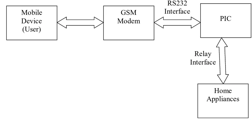
The project was based on the principle of GSM network, which enables the user to remotely control the operations of the appliances by using a mobile phone. In other words, it would transform a normal home into an intelligent home. The controlling circuit is the most important component in communication and interface between home appliances. It was implemented by using Peripheral Interface Controller (PIC) interfaced to mobile phone. The user can perform ON/OFF operations of the appliances just by pressing keypad of mobile phone.
2
Relay Interface
and etc. The appliance may also provide the user with its current ON/OFF status. The system can be improved to provide the user with information about the status of each appliance.
A sketch of overall design of the home appliances control using GSM is shown in Figure 1.1.
[image:19.595.111.525.202.400.2]v
Figure 1.1: Simplified block diagram of home appliances control using GSM
1.2 Project Objectives
The objective of this project as follows:
i. To design and develop Home Appliances Control System over GSM network by using a mobile phone.
ii. To determine and understand on how the GSM works. iii. To understand the architecture and programming of the PIC. iv. To interface the GSM modem with the PIC.
v. To learn the troubleshooting and techniques. Mobile
Device (User)
RS232 Interface GSM
Modem PIC
3 1.3 Problem Statement
The most basic controlling device must have at least a switch. A few decades ago, controlling devices using remote control switches like infrared (IR) and Radio Frequency (RF) were already popular but these technologies have their own limitations and bandwidth. Some technologies like IR remote control are only used for short distance applications.
In case of users going oversea or outstation, the remote control technology using IR and RF is not suitable due to range limitation. In other word, user is unable to control the appliances if user not at home. For example, user cannot randomly turning lights on and off. Hence, it may enable thief to break into their homes. Furthermore, the user may waste lot of energy by not switching off the appliances when not in use.
Hence, this project is designed and developed to overcome these problems. A success project may help the user control their appliances at home by using the mobile phone. To be precise, this project will enable the user to control the ON/OFF of the devices, with a single push of a button or a few more. It will also enable the user to check the appliances status from time to time.
1.4 Scope of the Project
The scopes of works in this project are:
i. Mobile phone with SIM card enables the user to remotely control the operations of the appliances by communication to the GSM modem. ii. GSM modem allows the capability to send and receive SMS to and from
the mobile phone.
4 iv. PIC microcontroller will be interfaced to the control circuit that is
connected to the appliances. It contains the software components through which the appliances are controlled and monitored.
v. C programming language is desired for the system’s program. The program is then compiled and executed before completed.
vi. Power circuit provides DC power supply through voltage regulator 7805 to 5 volt.
vii. Relay and control circuit used to detect and control the condition of the home appliances.
1.5 Methodology
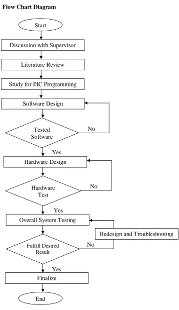
Based on the flowchart from Figure 1.2, the project starts by discussing several possible topics with the supervisor. After a topic has been selected, additional discussions were done in order to understand the concept and objective of the project. Then, literature review was done and the background of this project was studied by referring to various sources such as journals, articles, reference books, internet, lecture notes and data sheets. All the information related to components, GSM and PIC was searched and the most suitable would be selected to be used in this project.
The C programming is studied, developed, simulated and executed. The software design includes interfacing between mobile phone, GSM modem, control circuit, PIC and home appliances.
The next step is hardware design, assembly of components will be carried out in stages, and devices will be connected to one another to form the complete system. The wire connection for the system is determined and control circuit for this system will be design in this stage.
5
6
Yes
No
Yes
No
Yes
[image:23.595.145.503.64.681.2]No 1.5.1 Flow Chart Diagram
Figure 1.2: Flow Chart Diagram Start
Discussion with Supervisor
Tested Software
End Hardware
Test
Fulfill Desired Result Literature Review
Study for PIC Programming
Software Design
Hardware Design
Overall System Testing
Redesign and Troubleshooting
7 1.6 Report Structure
This report consists of five chapters. Following is a chapter-by-chapter description of report.
Chapter 1 is the introduction of how the idea of this project generated. The chapter contains introduction, objective of the project, problem statement, scopes of project, brief methodology and report structure.
Chapter 2 contains the literature review on theoretical concepts applied in this project. The chapter concludes the background study of Global System for Mobile communications (GSM), PIC16F877A, RS232 interface and application of other components. This chapter also contains the theory of the components, equipments, software and programming languages that is used in the project.
Chapter 3 contains the hardware design of the project. It is mainly about the construction of the project, which involves circuit design.
Chapter 4 involves the software development of project. The chapter will discuss on interfacing device on this project by using C programming. This chapter contains the programming flow chart which describes the program flow of the software.
Chapter 5 will cover all results from the designing process to the end. The chapter concludes with discussion all outcomes of this project and the design process. The testing procedures, devices and method used to generate the expected results are also included in this chapter. This chapter will feature a few tests that have been conducted.