ii
“I hereby declare that I’m the author of this report and it as a result of my own work, except a few sections which were extracted from other resources as being mentioned”
Student’s Signature : ……….
Name : Alyaa Izzati Hashim
iii
ACKNOWLEDGEMENT
I would like to express my deepest thanks to En. Hamzah who is my supervisor that always guides me in completing this final project report. I’m also wanted to extend my appreciation to En. Ahmad Rivai who also helps and guides me.
To my family members also I would to say thank you for their continual support and encouragement has been unending and unconditional, as is my love for them. All of my friends who are supporting me, I also want to extend my appreciation to them.
iv
ABSTRACT
There are many type of test for materials to determine material properties at high strain rate. The most commonly used method is the split Hopkinson bar test and it is also known as Kolsky bar. The high strain rate is approximately in ranges 104 in/in/sec. The design of this device is presented in research, design, and measurement.
The overview of the split Hopkinson bar test are it is consists of two steel bar that sandwich a cylindrical specimen between them. One of the bars is striked by the striker bar, a compressive stress wave is generated that immediately begins to transverse towards the specimen. When it arrives at the specimen, the wave partially reflects back towards the impact bar end. The other part of the wave will transmit through the specimen and into the second bar causing the plastic deformation in the specimen. It is shown that the reflected and transmitted waves are proportional to the specimen’s strain rate and stress. Specimen strain can be determined by integrating the strain rate.
v
ABSTRAK
Dari dulu hingga kini juruterkajian untuk menghasil suatu cara yang terbaik untuk menentukan kadar ketegangan yang tinggi pada sesuatu bahan. Split Hopkinson Bar Test merupakan suatu cara yang biasa digunakan untuk menentukan kadar ketinggian ketegangan sesuatu bahan. Kadar ketinggian ketegangan sesuatu bahan biasanya dalam angaran 104 in/in/sec. Dalam proses mereka bentuk split Hopkinson bar test ini kajian menyeluruh mengenainya perlu dilakuakan.
Gambaran sebenar split Hopkinson bar test ini adalah dua bar yang di tengah-tengahnya terdapat satu bahan contoh. Salah satu daripada bar tersebut iaitu dikenali juga sebagai input bar di langgar dengan kuatnya oleh satu bar lain. Semasa perlanggaran berlaku satu gelombang tekanan terhasil dalam input bar atau impact bar. Apabila gelombang ini menyentuh permukaan bahan contoh tersebut sebahagian daripada gelombang tersebut terpantul kembali ke dalam input bar dan sebahagian lagi akan merentasi bahan contoh dan bar yang satu lagi atau output bar. Ini menunjukan bahawa gelombang yang merentasi dan memantul adalah berkadar terus dengan kadar tekanan bahan contoh itu.
vi
1.4 Overview of Split Hopkinson Bar Test 2
CHAPTER 2 LITERATURE REVIEW
2.1 Introduction 3
2.2 History Perspective 4
2.3 Strain 4
2.4 Stress-Strain Rate 5
vii
CHAPTER DESCRIPTION PAGES
2.6 An Experiment Using Plasticine to Show The 9 Wave Generate in Bar
2.7 Theory of Split Hopkinson Bar 11
2.8 Equation of Motion of Striker Bar 14
2.9 Design of SHBT 15
2.9.1 The Design from Southwest Research 15 Institute
2.9.2 The Design from University of Maine 17 2.9.3 Function of Each Component 18
CHAPTER 3 METHODOLOGY
3.1 Introduction 19
3.2 Concept Design 19
3.3 Design Description 20
viii
CHAPTER DESCRIPTION PAGES
4.8 Stand 27
4.9 Strain Gauges 28
4.10 Summary of Overall Part and Component 30
4.11 Final Design of SHBT 31
4.12 Theoretical Calculation of Motion of Striker Bar 32
CHAPTER 5 DISCUSSION
5.1 Introduction 33
5.2 Strain Gauges Measurements 33
5.3 Testing Procedures 34
5.4 Data Processing Procedures 37
ix
LIST OF TABLES
NO. TITLE PAGES
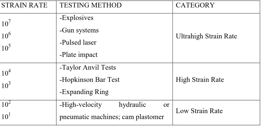
2.1 Testing Technique According to Strain Rate 6
2.2 Apparatus of SHBT in early 1960 in SwRI 15
2.3 The improvement of SHBT apparatus in early 1970 15 in SwRI
2.4 Function of each component of SHBT 17
4.1 Dimension of I-beam 28
4.2 Summary of apparatus in SHBT 30
4.3 Summary of component in SHBT 30
x
LIST OF FIGURES
NO. TITLE PAGES
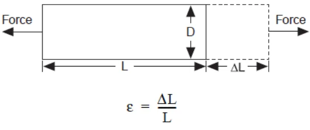
2.1 Definition of strain 5
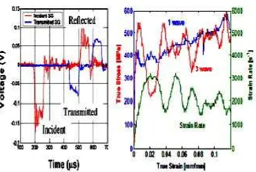
2.2 Shows propagation waves on left and strain on right 8
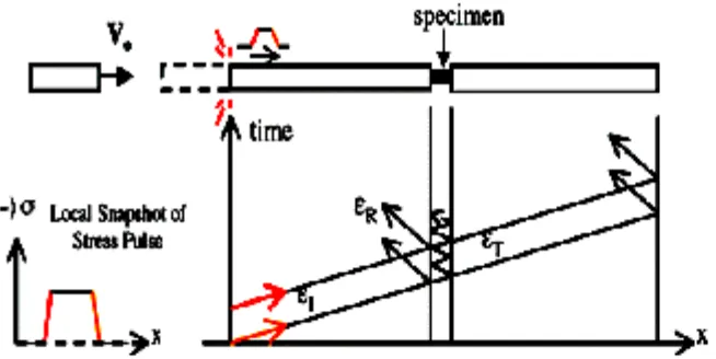
2.3 Shows the reflection and absorption of the wave 9
propagation wave
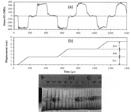
2.4 a) Plot of stress pulse profile recorded by the strain gauges on 10 transmitter bar, b) calculated displacement history at the bar
plasticine and c) cross-sectional view of the recovered plasticine after being subjected to the displacement history
2.5 Schematic drawing of SHBT 11
2.6 Free body diagram of striker bar 14
2.7 Shows a diagram of the apparatus 17
3.1 Flow diagram of the design 21
xi
4.2 Launching tube 26
4.3 Figure of I beam 28
4.4 Stand 28
4.5 Schematic of SHBT 29
4.6 Results of SHBT design 31
5.1 Block diagram of SHBT scheme 35
5.2 Block diagram of typical data processing procedure 37
5.3 Expected incident wave 37
xii
LIST OF SYMBOL
ax = acceleration
P = initial pressure of compressed air tank A = area of the projectile
L = travel distance (barrel length) m = mass of the projectile
1
CHAPTER 1
INTRODUCTION
1.1 PROBLEM STATEMENT
High speed impact is not so easy to reproduce in testing and therefore usually use bullet impact is used for high speed test. Nowadays in a few development country the split Hopkinson bar apparatus has quickly become the most widely used device to test materials at high strain rates. The purpose of this study is to improve the current testing techniques and to design our own high speed impact test machine using Hopkinson bar principle.
1.2 OBJECTIVES:
1 To study the Hopkinson bar test development
2 To study the technique of high speed impact measurement system
2
1.3 SCOPE OF PROJECT:
1 Literature research to understand high speed impact and measurement system 2 Collect the data of Hopkinson bar test development
3 Design of impact test machine, consist of: - Rig design: impacter and specimen holder - Measurement system
4 Measurement system calibration 5 Report writing
1.4 OVERVIEW OF SPLIT HOPKINSON BAR TEST
The materials are stronger at higher strain rates, which are caused by an impact. The behaviour of the materials attract the engineer to do more research about this problem and to come out with the design that can test and measure the strain rates of the materials. One of the devices that is most widely used to test materials at high strain rates is Split Hopkinson Bar Test (SHBT) and it is also the most commonly used method for determining material properties at high rates of strain.
3
CHAPTER 2
LITERATURE REVIEW
2.1 INTRODUCTION
Materials are stronger at high strain rate that caused by an impact. The behaviour of structure to impacts attracts the engineers for purpose of design the constitutive models of materials tested. The SHBT has become widely and commonly used method for testing high strain rate. Constant strain rate tests can be performed at strain rates approaching 104 s-1 relative easily.
4
2.2 HISTORY PERSPECTIVE
a) Betram Hopkinson(1913) was the one who found out and introduces a technique for determining the pressure-time relations due to an impact. Hopkinson’s idea was that as by impacting one end of the rod, a compressive pressure wave is generate inside the rod and as the compressive wave traversed through the bar, it will reflected back as a pulse of tension at the free end.
b) Davies(1948) was the one who improving the accuracy of Hopkinson’s original apparatus by using condensers to measure strains. He was develops a technique using condensers to measure the strains existing in the pressure bar.
c) Kolsky an Investigation of the Mechanical Properties of Materials at Very High Rates of Loading, Proc. Phys. Soc. London (1949). adds a second bar to Hopkinson’s original apparatus and he name it as split Hopkinson bar which is Kolsky sandwiched a specimen between two bars. He expressions the calculation of the specimen based on the strain histories and the strain were measured using the condenser used by Davies. The Kolsky’s idea has become the most widely used testing for high rate test today and the split Hopkinson bar also referred by Kolsky bar.
d) Hauser(1970) add strain gauges to the split Hopkinson bar to measure surface displacements.
2.3 STRAIN
5
Figure 2.1: Definition of Strain (Source from www.strain.com)
Strain can be positive (tensile) or negative (compressive). Although dimensionless, strain is sometimes expressed in units such as in./in. or mm/mm. in practice, the magnitude of measured strain is very small. Therefore, strain is often expressed as micro strain ( ), which is . When a bar is strained with a uniaxial force, as in Figure 2.1, a phenomenon known as Poisson Strain causes the girth of the bar, D, to contract in the transverse, or perpendicular, direction. The magnitude of this transverse contraction is a material property indicated by its Poisson's Ratio. The Poisson's Ratio of a material is defined as the negative ratio of the strain in the transverse direction (perpendicular to the force) to the strain in the axial direction (parallel to the force), or
. Poisson's Ratio for steel, for example, ranges from 0.25 to 0.3. (reference: www.strain.com)
2.4 STRESS-STRAIN RATE
6
In the elastic region stress is proportional to strain. Initially the strain hardening more than compensates for this decrease in area and the engineering stress continues to rise with increasing strain.
(Reference: http://en.wikipedia.org/wiki/Stress-strain_curve)
Table 2.1 : Testing Technique According to Strain Rate
(Source from thesis of spectral analysis of wave propagation through a polymeric Hopkinson bar, University of Waterloo).
STRAIN RATE TESTING METHOD CATEGORY
107
pneumatic machines; cam plastomer Low Strain Rate
a) Taylor Anvil Test
7
b) Expanding Ring
This method uses a hollow cylinder with an explosive core as a method of initiating a shock wave. The material to be tested is placed in a ring around the hollow cylinder. As the explosive is detonated, the shock wave expands radially, which in turn causes the cylinder and specimen to expand. In order to determine the stress strain curve for the material, the velocity history of the ring is recorded. This method uses varying amounts of explosive to select the strain rate desired (source from thesis of spectral analysis of wave propagation through a polymeric Hopkinson bar, University of Waterloo).
c) Split Hopkinson Bar Test
The Split Hopkinson Bar comprised of three separate bars known as the striker bar, incident and the transmitter bar. The striker bar is propelled towards the incident bar at a desired velocity. A compressive wave is imparted into the incident bar as the striker impacts. Some of the wave in the incident bar is transmitted through the sample into the transmitter bar and the rest of the wave is reflected in the incident bar. In order to determine the strain within the sample, strain gauges are mounted on both the incident and transmitter bars (source from thesis of spectral analysis of wave propagation through a polymeric Hopkinson bar, University of Waterloo).
8
2.5 WAVE PROPAGATION
Figure 2.2: Shows propagation waves on left and strain on right (source: University of Maine)
9
Figure 2.3: Shows the refraction and absorption of the wave propagation waves. (Source: University of Maine)
Using one dimensional wave propagation analysis we can determine high strain rate stress-strain curves from the measurements of strain in the incident and output bars. In order to obtain correct wave propagation the striker bar must reach necessary velocity before it hits the incident bar.
2.6 AN EXPERIMENT USING PLASTICINE TO SHOW THE WAVE
GENERATE IN BAR
10
Figure 2.4: a) Plot of stress pulse profile recorded by the strain gauges on transmitter bar, b) calculated displacement history at the bar-plasticine and c) cross-sectional view of the recovered plasticine after being subjected to the displacement history.
11
2.7 THEORY OF SPLIT HOPKINSON BAR
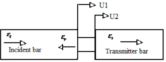
Figure 2.5 : schematic drawing of SHBT (Source from theory of split Hopkinson bar)
SHBT is consists of a striker bar, an incident bar, specimen under test and output bar. Wave equation:
Assuming a one-dimensional system, the strain in the incident rod is, by definition,
u
x (3)