Design and Development an Underwater Glider
using PIC for Monitoring Application
M. Faiz bin Sapee, M. Shahrieel M. Aras,
Faculty of Electrical Engineering, Universiti Teknikal Malaysia Melaka Email: [email protected] Faculty of Electrical Engineering, Universiti Teknikal Malaysia Melaka Email: [email protected]
Abstract— This project is described a design of an underwater glider using PIC as controller. Underwater glider is a type of autonomous underwater vehicle (AUV). Underwater Glider is a technology undergoing active and rapid development that uses small changes in its buoyancy in conjunction with wings to convert vertical motion to horizontal, and thereby propel itself forward with very low power consumption. The main purpose of this project is to design and develop an underwater glider controlled by PIC. This project is categorized to three major phase which is the mechanical design concept, programming and fabrication. The design and development of the underwater glider should be having hydrodynamic characteristics, stability and buoyancy.The movement of the underwater glider is controlled by PIC controller using C language program. The underwater glider that will be produced can move forward and reverse autonomously.
Keywords————Underwater Glider, PIC controller, AUV I. INTRODUCTION
The main purpose of this project is to design and
developed and underwater glider using PIC. Since nowadays there are many new kind of underwater glider have been developed till an advanced state. The development of the Underwater Gilder is presented as an example of the implementation process for a mechatronic product.
An underwater glider is an Autonomous Underwater Vehicle (AUV) that utilizes a small change in its buoyancy to convert vertical motions to horizontal ones with help of wings. Thus the underwater glider can move forward with low power consumption. Therefore, the underwater glider can be a small, smart and inexpensive which has a long operational time. The difference between conventional AUVs and underwater gliders are the dynamic behavior because of propulsion mechanism.
The driving force of the underwater glider depends on hydrodynamic forces such as drag and lift, which is a function of the advance speed and the angle of attack. This underwater glider project used PIC to control the movement of the underwater glider. For this
development of underwater glider, the underwater glider will have hydrodynamics characteristic, stability and dynamic buoyancy. This underwater glider will propel by electrical motor-driven propellers. Finally, the underwater glider will be produced and can move forward and reverse autonomously.
An Underwater Glider has been designed by using SOLIDWORK software before convert to the actual vehicle. The basic information about the remote control, hydrodynamic concept, buoyancy adjustment and motor will be implementing in this project.
Figure 1. The Design Flows of the Design and Development of Underwater Glider
III. THEORY
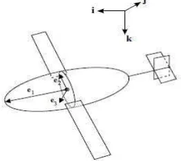
In this section the underwater glider model derived is adapted to model the Slocum glider design. This involves adjusting the parameters corresponding to the internal masses and the vehicle geometry. The model parameters are adjusted to match the Slocum body and wing shape [16]. First, take the underwater glider hull to be symmetrical with wings and tail attached so that the center of buoyancy (CB) is at the center of the hull. Then, assign a coordinate frame fixed on the vehicle body to have its origin at the CB and its axes aligned with the principle axes of the hull.
Let body axis 1 lie along the long axis of the vehicle (positive in the direction of the nose of the glider), let body axis 2 lie in the plane of the wings and body axis 3 point in the direction orthogonal to the wings as shown in Figure 2.
Figure 2: Frame assignment on underwater glider
The total stationary mass of the glider, ms, (also referred to as body mass) is the sum of three terms . mh is a fixed mass that is uniformly distributed throughout the body of the glider, mw is a fixed point mass that may be offset from the CB, and mb is the variable ballast point mass, also offset from the CB in the underwater glider. . The vector from the CB to the point mass is . The vector from the CB to the variable ballast mass is . The moving internal point mass is . The vector describes the position of this mass with respect to the CB at time t. The total mass of the vehicle is then:
(3.0)
The mass of the displaced fluid is denoted m and we define the net buoyancy to be , so that the vehicle is negatively (positively) buoyant if is positive (negative). The different masses and position vectors are illustrated in Figure 3.
Figure 3: Glider mass definitions
Here, consider this model specialized to the longitudinal plane (assumed invariant), as in [15], and solve for the equilibrium steady glides in the equations of motion. The resulting vertical plane equilibrium equations are:
(3.1)
(3.2)
(3.3)
(3.4)
(3.5)
corresponding to the and directions, as derived by Kirchhoff [13]. In these equations, take the added mass cross terms to be zero. Note that equilibrium terms corresponding to the offset mass and the location of the ballast mass do not appear in earlier model glider [15].
Figure 4: Lift and drag on underwater glider
As shown in Figure 4, denote the glide path angle by where:
At equilibrium, it may be shown that:
Denote the glider speed by V where:
Using Equation (3.2) and angle definition in Figure 4, the glider depth rate can be written as:
(3.6)
The hydrodynamic forces and moment are modeled as:
(3.7)
(3.8)
(3.9)
where are the standard aerodynamic drag, lift and moment coefficients by cross sectional area, A is the maximum glider cross sectional area, and is the fluid density. For the longitudinal quasi-steady fluid
model, are functions of and are constant coefficients.
IV. RESULT
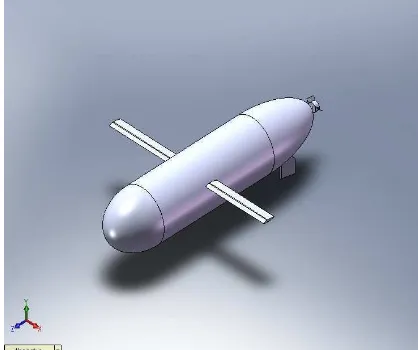
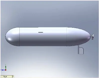
In every research and project, the main point need to focus is the results and findings. This section discussed about the result for design and for an Underwater Glider. At the end of this project, this underwater glider can be floats on surface of the water by using buoyancy concept. This underwater glider also can moves forward, reverse, turn right and turn left by using PIC through C programming. The result is a drawing of Underwater Glider which draws by using SolidWorks software. This design considers the design and dimension of the Underwater Glider body from the literature review but the dimension are changed after construct the actual vehicle. The design of Underwater Glider has been shown on Figure 5 (isometric view) and Figure 6 (Top view).
Figure 5. Design of Underwater Glider (Isometric View)
Figure 7. Dimension for the Length and Diameter of the Glider
Besides the PIC 16F877A, PIC Microcontroller Start-Up Kit is another device that used in this project. This board is shown in Figure 8. This board is designed perfectly fit for 40 pin 16F and 18F PIC that consists of all 33 I/O pins that are nicely labeled to avoid miss connection. This item developed with RS232 (Serial) hardware on board that allowing alternative method to load program easily via bootloader. The basic functionality of this board is shown in TABLE 1.
Figure 8: Board Layout
TABLE 1 BASIC BOARD FUNCTION
Label Function Label Function A Slide Switch
for main power supply
G 5V regulator
B DC power adaptor socket
H Header pin and turn pin
C Battery I 40 pin IC socket for
connector PIC MCU
D Power
indicator LED
J Reset button
E Serial cable adaptor (female DB9)
K Programmable push button
F Connector for UIC00A Programmer
The L293D as shown in Figure 9 is a quadruple high-current half-H driver. The L293D is designed to provide bidirectional drive currents of up to 600-mA at voltages from 4.5 V to 36 V. This device is designed to drive inductive loads such as relays, solenoids, dc and bipolar stepping motors, as well as other high-current /high-voltage loads in positive-supply applications. For this project, this device drives the DC motor for the movement of underwater glider.
Figure 9: L293D
This is the programming code for the movement of underwater glider.
void initmain() {
trisb=0; portb=0; trisc=0; portc=0;
PWM1_Init(5000); PWM1_Start(); }
void motor1fwd(int value1)
{ portb.f2=1; portb.f3=0; PWM1_Change_Duty(value1); } void motor1rev(int value1)
{ portb.f2=0; portb.f3=1; PWM1_Change_Duty(value1); } void motor1stop()
{ portb.f2==0; portb.f3==0; PWM1_Change_Duty(0); } void main()
{ initmain(); while(1) {
motor1fwd(250); delay_ms(10000); motor1stop(); delay_ms(200); motor1rev(250); delay_ms(10000); motor1stop(); delay_ms(200); }
V. CONCLUSION
As a conclusion, An Underwater Glider is a type of underwater vehicle. Underwater gliders are autonomous vehicles that profile vertically by controlling buoyancy and move horizontally on wings. This vehicle are valued for both their expand ability and replace ability. They can be deployed in hazardous environments without risking human divers. In addition, the Underwater Glider have a potential for cheap scalability makes Underwater Glider ideal for large scale and long term data collection tasks. This research aims to design and develop an Underwater Glider control by PIC which can float and moves on water surface with long time. The prototype that will be developed will have a fixed mechanical system and having an electronic part that allows development of various controllers.
There are a few functionality can be considerate to improve the development of the underwater glider. By adding the Global Positioning System (GPS), it helps to detect the position the underwater glider. Besides that, the improvement of underwater glider also can be done by adding the sonar sensor system. This sonar sensor system can help to transmit and to receive a signal from the obstacle. Therefore, it can avoid the underwater glider from violate the obstacles.
ACKNOWLEDGMENT
We wish to express our gratitude to honorable Faculty of Electrical Engineering and Universiti Teknikal Malaysia Melaka especially to higher management for give the financial as well as moral support complete this project successfully.
REFERENCES
[1] Davis, R. E., C. C. Eriksen, and C. P. Jones, 2002. Autonomous buoyancy-driven underwater gliders, In: Technology and Applications of Autonomous Underwater Vehicles, G. Griffiths, Ed., Taylor and Francis, London.
[2] H. Stommel. The Slocum mission. Oceanography, 2:22–25, 1989. [3] Y. Tomoda K. Kawaguchi, T. Ura and H. Kobayashi.
Development and sea trials of a shuttle type auv Albac. In Proc. 8th Int. Symposium on Unmanned Untethered Submersible Tech., pages 7–13, Durham, NH, 1993.
[4] T. B. Curtin, J. G. Bellingham, J. Catipovic, and D.Webb. Autonomous oceanographic sampling networks. Oceanography, 6:86–94, 1989.
[5] J. Sherman, R. E. Davis, W. B. Owens, and J. Valdes. The autonomous underwater glider ‘Spray’. IEEE Journal of Oceanic Engineering, Special Issue on Autonomous Ocean Sampling Networks, 26(4), Oct 2001.
[6] C. C. Eriksen, T. J. Osse, T. Light, R. D. Wen, T. W. Lehmann, P. L. Sabin, J. W. Ballard, and A. M. Chiodi. Seaglider: A long range autonomous underwater vehicle for oceanographic research. IEEE Journal of Oceanic Engineering, Special Issue on Autonomous Ocean Sampling Networks, 26(4), Oct 2001.
[7] C. C. Eriksen. Autonomous underwater gliders. Technical report, Prepared for the Autonomous and Lagrangian Platforms and Sensors (ALPS) Workshop, Sea Lodge, La Jolla CA, 2003. [8] WHOI Media Relations News Release. Underwater robot makes
history crossing the gulf stream. http:www.whoi.edumedia2004 Spray Release.html, November 4, 2004.
[9] D. C. Webb and P. J. Simonetti. A simplified approach to the prediction and optimization of performance of underwater glider. In Proc. 10th Int. Symposium on Unmanned Untethered Submersible Tech., pages 60–69, Durham, NH, 1996. [10] D. C. Webb and P. J. Simonetti. The SLOCUM AUV: An
environmentally propelled underwater glider. In Proc. 11th Int. Symposium on Unmanned Untethered Submersible Tech., pages 75–85, Durham, NH, 1999.
[11] C. C. Eriksen, T. J. Osse, T. Light, R. D. Wen, T. W. Lehmann, P. L. Sabin, J. W. Ballard, and A. M. Chiodi. Seaglider: A long range autonomous underwater vehicle for oceanographic research. IEEE Journal of Oceanic Engineering, Special Issue on Autonomous Ocean Sampling Networks, 26(4), Oct 2001.
[12] D. C.Webb, P. J. Simonetti, and C.P. Jones. SLOCUM, an underwater glider propelled by environmental energy. IEEE Journal of Oceanic Engineering, Special Issue on Autonomous Ocean Sampling Networks, 26(4):447–452, 2001.
[13] H. Lamb. Hydrodynamics. Dover, New York, 6thedition, 1932. [14] D. Webb and C. Jones. Slocum Three-view. Webb Research Co.
Technical Document. Courtesy Webb Research Co., 2002. [15] N.E. Leonard and J.G. Graver. Model-based feedback control of
autonomous underwater gliders. IEEE Journal of Oceanic
Engineering, Special Issue on Autonomous Ocean Sampling Networks, 26(4):633–645, 2001.