FIBER OPTIC BASED LINE FOLLOWING MOBILE ROBOT AZIZUL HALIM BIN ABD RAHMAN
“I hereby declared that I have read through this report entitle “Fiber Optic Based Line Following Mobile Robot” and found that it has comply the partial fulfillment for awarding the
degree of Bachelor of Electrical Engineering (Mechatronic)”
Signature : ……….
Supervisor‟s Name : Encik Muhammad Fahmi Bin Miskon
FIBER OPTIC BASED LINE FOLLOWING MOBILE ROBOT
AZIZUL HALIM BIN ABD RAHMAN
This Report is submitted in Partial Fulfillment of Requirements for the Degree of Bachelor in Electrical Engineering (Mechatronic)
Faculty of Electrical Engineering
UNIVERSITI TEKNIKAL MALAYSIA MELAKA
“I hereby declared that this report entitle “Fiber Optic Line Following Mobile Robot” is the result of my own work except as cited in the references. The report
has not been accepted for any degree and is not concurrently submitted in candidature of any other degree.”
Signature : ………
Name : Azizul Halim Bin Abd Rahman
ACKNOWLEDGEMENT
Alhamdulillah, thanks to Allah S.W.T the Final Year Project (FYP) is completed. I hereby would like to take this opportunity to thank all persons who has involved generously in helping me and assisting me while I was completing the Final Year Report (FYP) which is a compulsory to all Universiti Teknikal Malaysia Melaka (UTeM) students in order to complete our degree.
I would firstly to express my deepest gratitude and thanks to my project supervisor, Mr Fahmi bin Miskon for his undivided support morally and physically, assistance, guidance, tolerance, which proved to be invaluable as to completion my Final Year Project (FYP).
I also would like to thank the panel, Mr Hyreil Anuar Haji Kasdirin and Mr Mohd Shahrieel Bin Mohd Aras whose give me a good comment during my presentation in FYP1. I also would like to take this opportunity to express my appreciation to my family and friends for their patients, understanding and also for their undivided support that they had gave me throughout the completion of my project.
v
ABSTRACT
This project is about the motion of an automatic robot for the purpose of ROBOCON 2010 using line following method. There are few methods to build this line following mechanism and this project intends to focus on 2 methods which are binary algorithm method and Proportional Integral Derivative (PID) controller. These methods produced the same result in lower speed but we need the best method which is able to function in greater speed. Besides that, it also must move smoothly and able to turn perfectly. After a few testing, the result will be analyzed. The best method of line following will be selected and use for purpose of ROBOCON 2010. As we know, in ROBOCON time is precious and we only have limited time to complete the task.
ABSTRAK
vii
1.1 Introduction of project 1
1.2 Objectives 2
1.3 Scope of project 2
1.4 Problems statement 3
1.5 Organization of project 4
2 LITERATURE REVIEW 5
2.1 BRAM II line following mobile robot 5
2.1.1 BRAM II PID control algorithm 5 2.2 Transistor based line following mobile robot 9
2.2.1 Principal of robot 9
2.3 Vision-based line following robot controller. 11
3 METHODOLOGY 14
3.1 Overview 14
4 RESULT 27
4.1 Overview 27
4.2 Develop the prototype mobile robot 27
4.3 Binary algorithm 30
4.3.1 Implement line following programming. 30
4.3.2 Flow chart of line following program. 31
4.4.1 Transfer function of brushless DC motor 35
4.4.2 Graph of system using PID controller 38
5 ANALYSIS AND DISCUSSION 39
ix
LIST OF TABLES
TABLE TITLE PAGE
2.1 Table of Complete PID Controller 8
4.1 Signal output of sensor and description. 30
4.2 Action taken based on utput signal. 32
4.3 Parameter of Brushless DC motor 37
5.1 Time taken of robot at low speed(front) 42
5.2 Time taken of robot at medium speed(front) 42
5.3 Time taken of robot at high speed(front) 43
5.4 Time taken of robot at low speed(mid-front) 44
5.5 Time taken of robot at medium speed(mid-front) 44
5.6 Time taken of robot at high speed(mid-front) 44
5.7 Time taken of robot at low speed(mid-back) 45
5.8 Time taken of robot at medium speed(mid-back) 46
5.9 Time taken of robot at high speed(mid-back) 46
5.1 Time taken of robot at low speed(back) 47
5.11 Time taken of robot at medium speed(back) 48
5.12 Time taken of robot at high speed(back) 48
5.13 Time taken of robot at low speed(front) 53
5.14 Time taken of robot at medium speed(front) 53
5.15 Time taken of robot at high speed(front) 54
5.16 Time taken of robot at low speed(mid-front) 55
5.17 Time taken of robot at medium speed(mid-front) 55
5.18 Time taken of robot at high speed(mid-front) 56
5.19 Time taken of robot at low speed(mid-back) 57
5.2 Time taken of robot at medium speed(mid-back) 57
5.21 Time taken of robot at high speed(mid-back) 58
5.22 Time taken of robot at low speed(back) 59
5.23 Time taken of robot at medium speed(back) 59
LIST OF FIGURES
FIGURE TITLE PAGE
2.1 BRAM II Proportional Integral and Derivative Control 6
2.2 BRAM II Line Follower Robot 8
2.3 Line follower robot sensor position 10
2.4 Example of line tracking navigation 10
2.5 Transistor based line following mobile robot 11
2.6 Image taken from the robot view with and without fog. 13
2.7 Vision based line following mobile robot 13
3.1 Position of sensor at robot 19
3.2 4 meter straight line at Robocon 2010 field 19
3.3 Position of sensor at robot 22
3.4 Path of robot at Robocon 2010 field. 22
4.1 Prototype of mobile robot. 28
4.2 Side view of prototype mobile robot 28
4.3 Location of controller board at prototype robot 28 4.4 Location of sensor at prototype robot 28
4.5 Actual robot for Robocon 2010 29
4.6 Labeling of sensor for line following. 30
4.7 Flow chart of line following using binary algorithm method 31 4.8 Labeling of sensor for junction counting
turning and making decision 33 4.9 Flow chart of junction counting, turning and making decision 34
4.10 Output graph of PID control system. 38
4.11 Value of gain Kp, Ki, Kd 38
5.1 Location of sensor at actual robot for line following. 40
5.2 4 meter straight line at Robocon 2010 field 41
5.3 Graph for location of sensor at front. 43
5.4 Graph for location of sensor at mid-front. 45
5.5 Graph for location of sensor at mid-back. 47
5.6 Graph for location of sensor at back. 49
5.7 Location of sensor at actual robot for junction counting
turning and making decision 51
xi
5.8 Path of robot at Robocon 2010 field. 52
5.9 Graph for location of sensor at front. 54
5.1 Graph for location of sensor at mid-front. 56
5.11 Graph for location of sensor at mid-back. 58
5.12 Graph for location of sensor at back. 60
LIST OF ABBREVIATION
PIC : Programmable Intelligent Computer
DC : Direct Current
IFC : Interface Free Controller PSM : Projek Sarjana Muda
Sen : Sensor
ICSP : In-Circuit Serial Programming
xiii
LIST OF APPENDICES
APPENDIX TITLE PAGE
A Library function of IFC 67
CHAPTER 1
INTRODUCTION
1.1 Introduction of project
This project is about the motion of an automatic robot for the purpose of ROBOCON 2010. The main objective of this project is to make the automatic robot move by following the line. To build this project, there are few devices that needed such as controller board, digital sensor and fiber optic cable.
This project is divided in 3 parts which is mechanical part, electrical and electronic parts and software part. Mechanical part involved building the prototype of the robot. The prototype of robot is important because of it is needed for testing the programming of line following programming.
2 There are few methods to build this line following mechanism and this project intends to focus on 2 methods which are binary algorithm method and Proportional Integral Derivative (PID) controller. These methods produced the same result in lower speed but we need the best method which is able to function in greater speed. Besides that, it also must move smoothly and able to turn perfectly. As we know, in ROBOCON time is precious and we only have limited time to complete the task.
The program for both binary algorithm and PID controller is using C language. It will be implementing and compile to HEX file by using MPLab software. Then it should be downloaded to PIC by using USB In-Circuit Serial Programming (ICSP) PIC programmer.
1.2 Objectives
The objectives of this project are:
1. To design a line following mobile robot for ROBOCON 2010.
2. To implement line following mobile robot by using binary algorithm.
3. To implement junction counting and decision-making line following mobile robot. 4. To implement line following mobile robot by using PID controller.
1.3 Scope of project
1. Mechanical parts
Scope of project in mechanical part is to build the prototype of automatic mobile robot. This prototype robot not necessary follows the specification of ROBOCON 2010 because it only use for testing the robot‟s behavior of line following using binary algorithm method and PID controller method.
Scope of project in electrical and electronics part is selecting the suitable devices for line following mobile robot. This project only use the devices that already have at the previous robot of ROBOCON such as LINIX brushless motor and VEXTA brushless motor, Interface Free Controller(IFC) and AR40B controller board, SUNX digital fiber sensor.
3. Software parts.
Scope of project in software parts is to implement the programming of line following mobile robot. This project only focuses on line following using binary algorithm and PID controller. Then line following using both methods will be test and comparing the result. At the end of this project, the best method of line following will be selected and use for purpose of ROBOCON 2010.
1.4 Problem statements
From ROBOCON 2009, we have a problem with the line following mechanism. During last year competition, we used binary algorithm line following as the mechanism for automatic carrier robot and we detected a few problems when using this binary algorithm method.
For last year automatic carrier robot, we used lower Pulse Width Modulation (PWM) meaning that the robot moves in lower speed. When it was tested in medium PWM, found that the robot always lose control and failed to continue following the line. This problem made the robot move slow to complete the task of ROBOCON 2009. The automatic carrier robot was also offset from line. It took a long time to return back to the line. It would make the team losing so much time and we only had 3 minutes to complete the task.
4 than that, the robot also has a problem when counting junctions but it is just a minor problem and not caused by the method that we used.
To solve this problem, PID controller method will be trying as an alternative way and compare the result of this method with the binary algorithm method. Lastly, we will improve the selected method to make it more accurate to be used in ROBOCON 2010.
1.5 Organization of the project
This report will be conducted in few chapters and each stated as below: Chapter 1: Introduction.
This chapter will explain about the project. It also consists of objective, scope of project and problem statement.
Chapter 2: Literature review.
This chapter will explain about the other project that related with this project. Chapter 3: Methodology.
This chapter will describe the method to build the prototype robot and the line following mechanism. It also explains the method of analysis that will be implementing for this project.
Chapter 4: Result.
This chapter will show the final result of the project. Chapter 5: Discussion and analysis.
This chapter will show the output of analysis and its discussion. Chapter 6: conclusion and recommendation.
CHAPTER 2
LITERATURE REVIEW
2.1 Literature Review 1
Title : BRAM II line follower Mobile Robot Author : Ronald Willem Besinga [1]
6 2.1.1 BRAM II Proportional, Integral and Derivative Control Algorithm
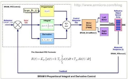
Figure 2.1: BRAM II Proportional Integral and Derivative Control
From the diagram above you could see how I implement the PID control on the BRAM II Line Follower Robot. The BRAM_PIDControl() function get the reflective object sensor array output from the BRAM_IRSensor() function and calculate the required control response to steer correctly the BRAM II DC motors by supplying the required PWM value to the BRAM_DriveMotor() function.
The “Proportional Control” is used to fix the error produced by the line follower robot position toward the black tape line compared to reference value (TARGET_VAL) which represents the robot position is at the center of the line. Therefore we could write down the error function as this following formula:
The proportional control actually works similar to the gain (volume) control found at the stereo set where it could increase or decrease the music volume came out from the speaker, the ears act as the sensors which give a feedback to the brain, while the target value is the preference music volume level. If the music volume level suddenly become higher compared to the preference level (error occur) than it decrease the volume level and vice verse. This gain factor usually called as the Kp (proportional) factor in PID control term. Therefore it could right down the control response as this following formula:
RESPONSE = Kp x ERROR
Using just the “Proportional Control” alone will resulting the zigzag steering behavior of the robot, therefore it have to combine with “Integral Control” or “Derivative Control” or both of them to produce more accurate and stable robot‟s steering movement. The following is the industrial standard PID control mathematic formula:
The “Integral Control” is used to reduce the accumulated error produced by the proportional control over the time or it‟s also called a steady-state error, therefore the longer the robot produces an error (not in the center of the black line) the higher the integral control response output value.
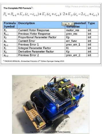
8 Table 2.1: Table of Complete PID Controller
2.2 Literature Review 2
Title : Transistor based line following mobile robot Author : Nikhil D Kelkar, Ronald Willem Besinga
This journal described line following mobile robot using transistor as a sensor. Disadvantage using the transistor on its linear region to control the DC motor‟s speed is the power dissipation (power loss as heat) on the transistor especially if it use large power DC motor, the common and efficient method to control the motor‟s speed is to use the PWM (pulse width modulation) which make the transistor on and off rapidly; but for the DC motor used in this line follower robot it could take the advantage of the transistor in its linear region.
2.2.1 Principal of transistor based line following mobile robot.