A CONTROLLER DESIGN FOR AN EXPANSION VALVE
MOHD HAFIFI BIN MUHAMMAD HANAFIAH
SUPERVISOR APPROVEMENT
“I hereby declared that I have read through this report and found that it has comply the partial fulfillment for awarding the degree of Bachelor of Electrical Engineering
(Control, Automation and Instrumentation).”
A CONTROLLER DESIGN FOR AN EXPANSION VALVE
MOHD HAFIFI BIN MUHAMMAD HANAFIAH B010410036
This Report Is Submitted In Partial Fulfillment Of Requirements For The Bachelor Degree of Electrical Engineering (Control, Automation and Instrumentation)
Faculty Of Electrical Engineering Universiti Teknikal Malaysia Melaka
“I hereby declared that this report is a result of my own work except for the excerpts that have been cited clearly in the references.”
Signature :………
Name : MOHD HAFIFI BIN MUHAMMAD HANAFIAH Ic / No : 850530-01-5797
iii
ACKNOWLEDGEMENT
Thanks God because gives me spirits and confidences in completing the whole project within the correct time. Throughout my project session, I have been guided by my supervisor and my entire colleague.
Here I would like to take this opportunity to express my deepest gratitude to my supervisor Pn. Sahazati Binti Md. Rozali for guiding and imparting her knowledge in every sector of my final project.
I also would like to thanks to UTeM especially for Faculty of Electrical Engineering, for giving me changes to be creative and innovative in electrical engineering. With these opportunities, I got clear understanding in electrical concept and learn how to think and build new equipment. Consequently, I would like to thank all individual who make sure this project is success.
v
ABSTRACT
ABSTRAK
vii
CONTENTS
CHAPTER TITLE PAGE
SUPERVISOR APPROVEMENT
PROJECT TITLE i.
DECLARATION ii.
DEDICATION iii.
ACKNOWLEGEMENT vi.
ABSTRACT v.
ABSTRAK vi.
CONTENT vii.
LIST OF FIGURE x.
LIST OF TABLE xi.
1 INTRODUCTION 1
1.1 INTRODUCTION OF THE PROJECT 1
1.2 OBJECTIVES 2
1.3 SCOPES OF WORKS 2
1.4 PROBLEM STATEMENT 2
1.5 PROBLEM SOLVING 2
2 LITERATURE REVIEW 3
2.1 SIMULATION MODEL OF A VAPOR COMPRESSION
REFRIGERANT SYSTEM 3
2.2 RESEARCHES ON DYNAMIC SIMULATION AND
SYSTEM
2.3 THERMOSTATIC EXPANSION VALVE BY KENNETH A.
CANGELOSI 5
2.4 EXPANSION VALVE BY ADDISON WESLEY (1953) 8 2.5 CAR AIR-CONDITIONING SYSTEM 9 2.5.1 COMPRESSOR 10 2.5.2 CONDENSER 10 2.5.3 EVAPORATOR 11 2.5.4 THERMAL EXPANSION VALVE 12 2.5.4.1 SUPERHEAT SETTING 12 2.5.4.2 EXTERNALLY EQUALIZED 13 2.5.4.3 VALVE HUNTING 14 2.5.4.4 BALANCED PORT VALVES 14 2.5.4.5 DOUBLE PORTED BALANCED PORT VALVES 14 2.6 CAR AIR CONDITIONING TIPS 14
3 PROJECT BACKGROUND 16
3.1 PROJECT THEORY 16
3.2 ANALOG-TO-DIGITAL CONVERTER 19 3.3 PULSE-WIDTH MODULATION 21 3.4 COMPONENTS USED IN THIS PROJECT 23 3.4.1 MICRO-CONTROLLER- PIC16877A 24 3.4.2 RC SERVO MOTOR 25 3.4.3 TEMPERATURE SENSOR (LM335) 26
3.5 PIC I/O PORTS 29
4 METHODOLOGY 31
4.1 METHODOLOGY OF THIS PROJECT 31 4.2 FLOW CHART (PROJECT METHODOLOGY) 33
ix
5 PROJECT RESULT AND ANALYSIS 35
5.1 OPERATION OF THIS PROJECT 35
5.2 OPERATION FLOWCHART 37
5.3 RESULT AND ANALYSIS 38
5.4 HARDWARE PARTS 39
5.5 SOFTWARE PARTS 41
6 DISCUSSION 46
6.1 DISCUSSION ON PROJECT OBJECTIVES AND SCOPES 46 6.2 DISCUSSION ON PROJECT ACTIVITIES 47 6.3 FUTURE ENHANCEMENT AND DEVELOPMENT 49
7 CONCLUSION 50
7.1 CONCLUSION OF THIS PROJECT 50
LIST OF FIGURES
FIGURE TITLE PAGE
2.1 Thermostatic Expansion Valve 5
2.2 Capillary Tube 6
2.3 Metering Piston 6
2.4 Pressure difference between the two sides 8
2.5 Car air-conditioning systems 9
2.6 Compressor 10
2.7 Condenser 10
2.8 Evaporator 11
2.9 Thermal Expansion Valve 12
2.10 TXV 13
2.11 Thermostatic Expansion Valve 15
3.1 Pressures in expansion valve 17
3.2 Inside expansion valve 18
3.3 How expansion valve connect with evaporator 18
3.4 Duty cycle general 21
3.5 A simple method to generate the PWM pulse train 22 3.6 PMW signal controlling servo motor 23
3.7 PIC16877A pins diagram 24
3.8 RC servo motor 25
3.9 Model C55S 26
3.10 Temperature sensor 26
3.11 TO-92 plastic package- bottom view 27
3.12 LM335 dimensions 28
xi
3.14 Basic connection of I/O 29
3.15 Type of connection I/O 30
4.1 Flowchart of project methodology 33
5.1 Operation flowchart 37
5.2 Front view 39
5.3 Rear view 39
5.4 Servo motor controlling valve 40
5.5 PIC board 40
LIST OF TABLE
NO TITLE PAGE
3.1 Time to set servo motor position 23 3.2 Comparison the model of servo motor 26
3.3 Temperature accuracy 28
4.1 Gantt Chart 34
5.1 Result of this project 38
CHAPTER 1
INTRODUCTION
This chapter discuss about introduction, objectives, scope, and problem statements for this project.
1.1 INTRODUCTION OF THE PROJECT
The purpose of this project is to model and design an expansion valve in a car air-conditioner system. It will be pursued by designing an embedded controller for the system using PIC. The project involves hardware and firmware parts. This project is a different method for controlling car air-conditioner expansion valve.
2
1.2 OBJECTIVES
1. To model and design an expansion valve for an air conditioner system.
2. To implement the electrical circuit wiring, PIC programming to control the sequence of the system and for troubleshooting.
3. To learn more on troubleshooting and solving problem.
1.3 SCOPE OF WORKS
1. To model and design an expansion valve for car’s air condition system. 2. To design a controller for the system using PIC16F877A.
3. To learn the concept of microcontroller (PIC) and micro-C programming to get finest tune.
4. To use RS-232C serial port as an interface between PIC controller & computer system.
1.4 PROBLEM STATEMENT
1. The original expansion valve system consist the 100% mechanical part. There are no variable situations in operating system.
2. In the expansion valve system, there have the delay due to the response of the sensing bulb.
1.5 PROBLEM SOLVING
CHAPTER 2
LITERATURE REVIEW
This chapter will explain the theoretical part of the component and information on the overall trends that will use in this project. This chapter also contains previous work related to this project.
2.1 SIMULATION MODEL OF A VAPOR COMPRESSION
REFRIGERATION SYSTEM, BY H. YASUDA, S. TOUBER & C.H.M. MACHIELSEN, 1983
4
2.2 RESEARCHES ON DYNAMIC SIMULATION AND OPTIMIZATION OF AUTOMOBILE AIR-CONDITIONING SYSTEM BY XUEJUN SUN, WEIHUA LIU, XIONGCAI QUE & ZHIJIU CHEN, 1999
The heat exchangers are modeled using a moving-boundary approach with each zone (liquid-phase, two-phase & superheated-phase) modeled in the lumped parameter
form. Equations of mass and energy conservation are applied to each phase along with the heat exchange equations through the heat exchanger wall to the secondary fluid (air). The equations for the refrigerant side use the void fraction concept for each zone,
treating the liquid zone as having a void-fraction of 0 and the superheated zone as having a void-fraction of 1. The length of each zone is inherent in the mass and energy
conservation equations for that zone.
The thermostatic expansion valve is modeled using a thermal-inertia delay for the sensing bulb. The sensed superheat is translated into a pressure signal, which is
applied to the diaphragm force balance to determine the nozzle area. This nozzle area and the pressure difference across the valve are used to determine the mass flow rate.
The orifice tube is modeled by the orifice equation and has no ‘input’ signals from the evaporator.
The system modeled includes both a receiver and an accumulator, since either
(but not both) can exist on any given system. In both these components, the refrigerant is modeled in its liquid and vapor phases as lumped parameters, in thermal equilibrium, and exchanging mass and energy of the phase-change. In both these components, both
In the compressor model, individual strokes are not considered and the complete
compressor model consists of a mass balance between suction and discharge and an energy balance between the polytrophic work of compression, enthalpy rise of the refrigerant, thermal capacitance of the compressor wall (lumped) and the heat
transferred to the ambient from the compressor wall.
In addition to the system components, the passenger compartment is modeled
using a discredited disturbance-response transfer function, with the disturbances being the environment temperature and radiant heat and the responses being the cooling load and the compartment temperature.
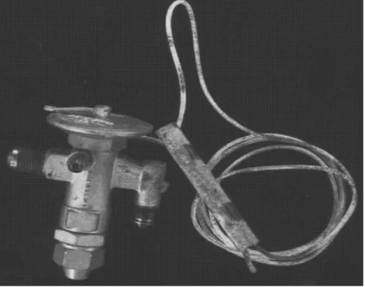
2.3 THERMOSTATIC EXPANSION VALVE BY KENNETH A. CANGELOSI
Figure 2.1: Thermostatic Expansion Valve
Figure 2.1 shows the thermostatic expansion valve (TXV) was removed from
6
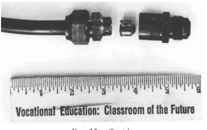
In the late 1980s, we saw a resurgence of TXV use as energy consumption became an important issue. There are two basic metering devices for refrigeration a fixed type and a modulating type. The fixed type used in the HVAC industry would be a capillary tube (see Figure 2.2) or a metering piston (see Figure 2.3). The modulating or regulating type would be the TXV.
Figure 2.2: capillary tube
Figure 2.2 shows the fixed type used in the HVAC industry would be a capillary tube
Figure 2.3 shows the fixed type used in the HVAC industry would be a metering piston
Adjustment of the thermostatic expansion valve is very important. The valve setting is determined by the amount of superheat in the refrigerant gas. Superheat is the temperature of the refrigerant gas above the temperature given by the pressure and temperature chart for the specific pressure. In air conditioning, most valves are set to 10°F superheat. The superheat determines the amount of liquid refrigerant mixed in the return gas. Too little superheat will cause the liquid refrigerant to damage the compressor. Too much superheat will cause poor evaporator coil performance and compressor overheating.
Proper valve sizing is also important. The valve capacity should be matched to the outdoor unit capacity. A valve that is too small will starve the outdoor coil or refrigerant and a valve that is too large will flood the compressor with refrigerant. All valves are rated in tonnage with 100 psig pressure drop across the valve. The higher the pressure drop, the more capacity the valve has. The lower the pressure drop, the lower the capacity.
8
The TXV has the ability to regulate refrigerant flow over a wide range of load conditions. The TXV has the ability to shut off refrigerant flow when the compressor stops. The TXV can help save on energy by adjusting refrigerant flow according to load. It can thus reduce the amount of energy used by the compressor. The TXV can also control the temperature of the compressor and keep its variance low through a wide range of changes in load.
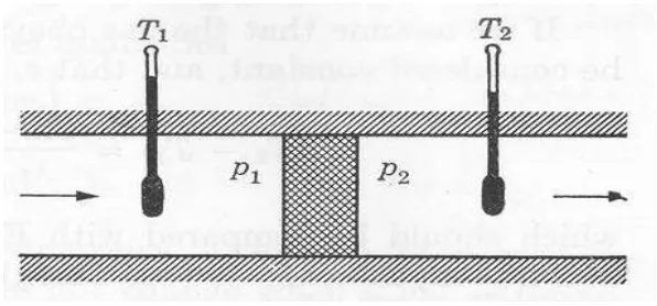
2.4 EXPANSION VALVE BY ADDISON WESLEY (1953)
The expansion valve is adjustable and controls the Freon flow through the system (and the pressure difference between the two sides). The inlet side of the valve is at high pressure and the Freon is a room temperature liquid at this location. In the expansion process, the pressure drops rapidly to the low pressure value and the Freon is superheated in this new pressure condition. The material then undergoes a partial change of phase, using its internal energy to provide the heat of transformation from the liquid to vapor phase. The reduction in internal energy is associated with a decrease in temperature of the two phase material exiting from the expansion valve.
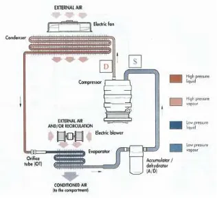
2.5 CAR AIR-CONDITIONING SYSTEMS
A typical car air conditioning system is diagrammed below. Refrigerant is pumped round in a cycle by the compressor. Refrigerants vaporize at very low temperatures e.g. -29 C. At the evaporator the liquid refrigerant absorbs heat from the air entering the car interior and boils off to a vapor. This has the effect of cooling the air. Cooler air can not hold so much moisture and this will be deposited on the evaporator. Vapor refrigerant then continues on its cycle to the condenser where air passing through it will cool the refrigerant back to a liquid again.
Figure 2.5 shows car’s air-conditioner system
10
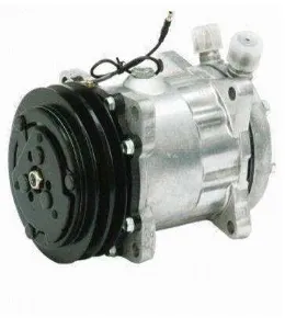
2.5.1 COMPRESSOR
Figure 2.6: Compressor
Figure 2.6 shows compressor used in car air-conditioners system. This is the heart of your air-condition system. The compressor is what takes the refrigerant (the gas) and pressurizes it so it will cool the air. It's run by an engine belt. The compressor also has an electrically operated clutch that turns the compressor on and off as you demands more cool air.
2.5.2 CONDENSER
Figure 2.7 shows condenser used in car air-conditioners system. The condenser is like a miniature radiator, usually mounted at the front of the car right next to your big radiator. Sometimes the condenser will have its own electric cooling fan, too. The hot, compressed air passes through the condenser and gets lots cooler. As it cools, it becomes a liquid.
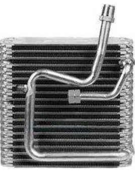
2.5.3 EVAPORATOR
Figure 2.8: Evaporator