Analysis of unimorph piezoceramic patches on damped square shaped
plate
Najib, A.M.
a., Fairul, A.J.
b, Bani Hashim, A.Y.
c, Hasib, H.
d, Muhammad, M.N.
e Faculty of Manufacturing Engineering, Universiti Teknikal Malaysia Melaka, Durian Tunggal,76100 Melaka, Malaysia
[email protected] a,[email protected] b, [email protected] c, [email protected] d, [email protected] e
Keywords: Piezo-element, Damping system, Finite element, Mode shape, Frequency.
Abstract. Active damping using piezoelectric element is one of the effective techniques to counter
vibration problems. A 3D finite-element model is developed as part of investigation for damping control. The piezoelectric patches are surface bonded on quadrilateral thin plate and supported with spring damper elements. The main goal of this paper is to investigate mechanical characteristics of piezoceramic array on membrane and the effect of force excitation using small motor and electric excitation on the system. The system setup produced small vibration displacement and does not displace the plate beyond elastic strain region. The results show the linear behavior of piezoceramic and the correlation between electric excitation, motor vibration and displacement at the centre of the plate at different frequency range. The mode shapes and natural frequencies at low frequency spectrum are also presented. Therefore, the results can be used as reference to develop damping system with aid of piezoelectric patches.
Introduction
There are numerous engineering applications employ thin structure and are subjected to variety of excitations and vibrations. Piezo-element on a thin structure has been studied by the different researchers for vibration control of membrane as well as structure monitoring and piezo-element emerged as a preferred vibration control mechanism. Distinctive mode shapes of thin structure with two piezopatches configuration can be determined using computer simulation and sand forming on the plate [1]. Meanwhile, several analyses with various numbers of piezo-element configurations have been carried out. Yaman et al. [2] analysed 5-patch configuration of piezo-element for clamped square plate while other configurations such as 9-patch and 12-patch configurations were studied by [3, 4]. Previous study by Halim and Moheimani [5] used varied piezo-element configuration for controlling dissimilar modes shapes and other researches by Gibbs and Fuller [6] and Fuller et al. [7] analyzed the effects of using piezoelectric patch as an actuator in rectangular beams. Recent advances in computer technology have given a capability for practical solution in developing and analyzing a system with the help of finite-element software before a full-scale system of a vibration control system is developed [8-11]. This study presents the finite-element analysis for thin plate structure excited by patches of piezoelectric transducer and force excitation from a vibration motor. Electrical and mechanical characteristics of 2-patch configuration for damped square plate at different excitations were investigated. Finally, mode shapes and natural frequencies were validated experimentally.
Finite Element Formulation
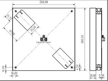
The model consisted of 200 x 200 mm rectangular steel plate with 0.5 mm thickness supported by 4 shock absorbers on a massive aluminum block (200 x 200 x 20 mm) to decouple any vibrations from the ground as shown in Fig. 1. A vibration motor was mounted at the centre of the plate together with sensors and used to generate mechanical disturbance that excited the plate modes and vibration measurement. The bandwidth of the disturbance was adjusted by varying the voltage
Applied Mechanics and Materials Vol. 315 (2013) pp 965-971 © (2013) Trans Tech Publications, Switzerland
doi:10.4028/www.scientific.net/AMM.315.965
excitation of piezoelement and the load of the motor. As higher voltages on motor load were applied, the more disturbances will be transmitted. There were two piezopatches of thickness 0.4 mm that were bonded on the top side of the plate with Hysol adhesive layer of thickness 0.2 mm.
Fig. 1 Thin plate structure, piezopatches and vibration motor.
The finite-element analysis involves a coupled electrical-structural problem that includes the vibration caused by motor and vibration transmitted from the electric excitation of piezopatches. The system involved strong coupling effect between mechanical and electrical quantities. The degree of freedom (DOF) of displacement field (Ux, Uy, Uz) are used for the structural analysis, whereas volt (V) is used for the electrical analysis. Finite element analysis is based on a set of constitutive equations. The equations describe the behavior of the coupled electromechanical problem in the analysis. The values of stress and electric displacement depend on the stress and the electric field quantity in the system. The constitutive equations used for the piezoceramic material are:
{T}=[ cE ]{S}-[e]{E}. (1) {D}=[ e]t{S}+[ S]{E}. (2)
where Tis the stress vector, Sis the strain vector, Dis the electric displacement vector ,E is the electric field vector, E
c is the stiffness matrix evaluated at constant electric field, e is the piezoelectric matrix related to stress/electric field, t
e is the piezoelectric matrix relating stress/electric field andS
is the dielectric matrix evaluated at constant strain.
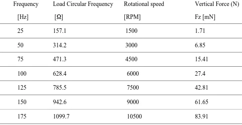
A SOLED45 3D element with 3 degrees of freedoms and 8 nodes is used for modeling the plate structure and bonding layer. The vibration motor is represented by MASS 21 structural point mass element with 3 degrees of freedoms (Ux, Uy, Uz). The mass of mounting parts for the vibration motor and the sensors are considered as constant acting on one node. The supports of the plate are modelled with COMBIN14 combination element with a DOF in longitudinal Uz direction and have 2 nodes. The base plate and the air are negligible. The MKS unit, Kg-m-s-A-K, is used for the modelling. The loads acting on the plate are generated from the vibrating motor and the actuation of piezoelement. The generation of vertical force on the plate comes from vibrating motor and is a result of eccentric mass rotating around its axis. The rotating mass creates centrifugal force, acting away from the centre of rotation. This force can be split as vertical and horizontal components. At lower operating frequencies, the effect of the horizontal force on the deformation of the system is very small compared to the vertical force. This assumption is supported by the experimental results. The calculation of the motor load leads to the following equation where
Fz represents the vertical
force.
Fz = me rΩ2 sin (rΩt). (3)
The eccentric mass (me) of the vibration motor is 0.0694 gram and the distance from the centre point of the eccentric mass to the axis of rotation is 1 mm and it is represented by radius (r). The forces are calculated by substituting the selected amount of load frequency (
).Table 1 below lists a set of calculated forces for various frequencies.
Table 1: Calculated force for load excitation from motor.
Frequency Load Circular Frequency Rotational speed Vertical Force (N)
[Hz] [Ω] [RPM] Fz [mN]
25 157.1 1500 1.71
50 314.2 3000 6.85
75 471.3 4500 15.41
100 628.4 6000 27.4
125 785.5 7500 42.81
150 942.6 9000 61.65
175 1099.7 10500 83.91
The boundary condition is divided into a few domains. In actuator mode, the piezoelement on the top plane is connected to the excitation voltage which is varied from 50 to -50 V and the plane has same voltage over the surface area of piezoelement. The bottom plane is grounded with zero potential. In sensor mode, the top surface is set as a floating electrode and the bottom surface the ground. The end of plate support which is connected to the base plate is clamped and all DOF are fixed. The other end of the support is fixed in x- and y-direction. The rotating mass of the vibration motor will produce force in vertical and lateral direction. The increment in vibration frequency is affecting the structure thermally, where molecular bonds are stretched, thus deforming the structure. The thermal deformation is given by:
ɛtherm = αT × ∆T. (4)
Since the linear coefficient of expansion of steel,
T
1 6
12 10 C
, is relatively small and the temperature difference,
T is considered small, the thermal deformation will be very small and negligible. The pressure at the bottom and the top of the plate have no difference and therefore,
P
= 0.
Electrical setup
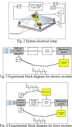
Fig. 2 shows electrical setup of the system. The mechanical system needs has first to be excited first in order to study the response characteristic of the system in frequency domain. Two forms of excitations used in the study are the electrical excitation and the force excitation. Piezoelectric element on the surface of the plate is oscillatable in response to electrical excitation. Both elements are driven via two channels piezo amplifier. The residual vibration in the middle of the membrane is acquired by a 3-axis acceleration-sensor ADXL330EB from AnalogDevices. The sensor output and the amplifier inputs are connected via ADC/DAC to a discrete control system. The signal processing will be realized accordingly using the graphical programming language of National Instrument´s LabVIEW.
Piezo-Fig. 3 Experiment block diagram for electric excitation
PC with
Fig. 4 Experimental block diagram for force excitation
To estimate the response characteristic of piezo elements, a swept-sine-signal is performed and the sensor signals are recorded by LABview application. The stimulus-signal is driven by the piezoelectric elements and the response-signal is the acceleration as shown in Fig. 3. In order to study the response characteristic of the force excitation on the system, the voltage of the motor is increased automatically with the help of a GPIB controlled power-supply. The output of the MSR- and the acceleration-sensor is recorded and handled via LABview application as depicted in Fig. 4.
Results
In this study, several types of analysis are used. Harmonic analysis is performed to investigate the amplitude response at various frequencies. This analysis gives the ability to predict the dynamic behavior of plate structure. Static analysis is used to calculate the value of maximum deformation of the applied force. Modal analysis is used to determine the mode shapes and natural frequencies whereas harmonic analysis is used to investigate the response of the system. Mode shape and natural frequencies are validated using experimental investigations.
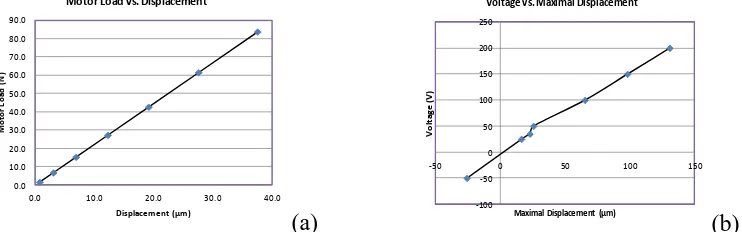
Static analysis. A specific load representing force from the motor in z-direction is applied at the
centre of the plate. Next, maximum deformations of the plate at various loads are determined. To investigate the general behavior of piezoelectric element and study the effect to the system, static analysis is used where the value of maximum deformation of the plate at different voltage
excitations has been calculated. Fig. 5 shows the result of the static analysis at various loads and voltage excitations. As the load increased from 0 to 80 N, the displacement at the centre plate is also
increased from 0 to 37 μm.
Fig. 5 (a) Static analysis of different motor loads, (b) Maximum deformation at various voltage excitations of piezoelement.
The piezoelectric expands laterally at positive voltage, and it produced extension at the upper plate and compression at the lower plate. The application of an electric field along the polarization direction makes the patches expand in the perpendicular direction, thus producing local strain on the patches that bends the plate upwards. A regional maximum occurs at the area where the piezoelectric patches are bonded with the plate, specifically at around the centre of the patch actuator at node 21416 and node 21417. As voltage excitations increased from 0 to 200 V, the plate deformed proportionally to the voltage applied. At -50 V, there is a contraction at the piezoelectric actuator. The application of electric field opposite the polarization direction makes the piezo actuator contract in the direction perpendicular to the electric field and bends the plate downward.
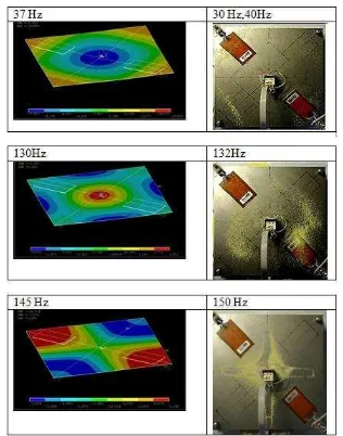
Mode shape and frequencies. Using ANSYS, The lancoz method was used as the extraction
method of the modes. The analysis will only investigate natural frequency and mode shapes within the frequency spectrum of 0 to 150 Hz. The mode shape and the natural frequency of the structure are calculated using modal analysis. Fig. 6 illustrates mode shape at the first three natural frequencies. The colours represent the magnitude in terms of displacement. The red represents maximum position; the blue represents minimum position, and the green are the neutral position which is equivalent to zero displacement. Natural frequency occurred at 37 Hz, and the corresponding Fig. 6 shows that the centre of the plate moves downward, and the four edges are in phase and move upward. The second mode shape at 130 Hz illustrates the mode shape of force excitation from the vibration motor. At second natural frequency, the centre plate moves to maximum point. All four side edges deform in upwards in phase direction. The neutral line is a circle touching the upper side of the piezopatch. The third natural frequency is found when the piezo patch is supplied with 50 V at frequency of around 145 Hz. The mode shape shows that edges at piezo patch side move to minimum point whereas the other two sides moves to maximum points. On right-side of Fig. 6 illustrates mode shapes from experiment at either the natural frequencies or its nearest natural frequencies using sand forming. Fig. 7 shows the resonance-frequencies of the mechanical system obtained using the electrical excitation of the piezo actuators as well as the force excitation of the vibration motor from the experiment. The comparison of the normalized magnitude shows a natural frequency at 30 Hz and somewhere at 126 and 147 Hz.
Harmonic analysis. Analysis of the harmonic response of the piezoelectric actuator is done to
obtain the dynamic behaviour of the plate structure. Different electric excitations were applied by varying supply voltage from -50 to 200 V to simulate a displacement response. Fig. 8 displays the response of the system at various voltage excitations. In the second analysis, finite element study was carried out for mechanical disturbance created by the vibration motor. Different force excitations were applied by varying the angular frequency of the rotation motor and the results are depicted in Fig. 9. From the graph, higher displacement responses were detected near and at the natural frequencies and the results are all true from experimental investigations.
Fig. 6 First three mode shapes of the system with experimental validation.
0 20 40 60 80 100 120 140 160 180 200 220 240 260 280 300 freq point (mag) [Hz] 0
0.2 0.4 0.6 0.8 1
MagnitudeMotor MagnitudePiezo
ph
as
e
[°]
ph
as
e
[°]
Fig. 7 Frequency response of system from experiment using electrical- and force excitation.
Fig. 8 Response of bonded piezoelectric element at various voltage excitations.
Fig. 9 Response at various motor loads.
Conclusion
The study concluded that the behavior of the plate with the piezo patch on applied input is linear at low frequency of 0 to 150 Hz. When the electric excitation is doubled, the plate displacement (centre plate) is also doubled. On the other hand, doubling the frequency of motor will result in an increment of displacement and vertical force as a factor of four. This correlation is true for all
frequency range. The applied input in the experiments and simulations resulted small displacement on the plate and therefore it follows linear characteristics. However if the displacements are high beyond elastic strain, the output will not follow the linear trend. Using FEA, the natural frequencies of the system at low frequency range are detected at 37, 130 and 145 Hz. The values are validated using experimental investigation. The mode shapes and natural frequencies from both the FEA and experiment analysis provided similar results with maximum of 3% deviation according to the natural frequency values. The investigations provided sufficient information about the system and can be used as references for development of a damping system at low frequency range.
References
[1] A.M.M. Najib, A.J. Fairul, Finite element analysis of plate structure excited by patches of piezoelectric actuators, Proceedings of Malaysian Technical Universities International Conference on Engineering and Technology, (2011) 834-838.
[2] Y. Yaman, T. Caliskan, V. Nalbantoglu, E. Prasad and D. Waechter , Active vibration control of a smart plate, ICAS 2002 Congress, (2002).
[3] L. Young-Hun, Finite-element simulation of closed loop vibration control of a smart plate under transient loading, Smart Materials and Structures 12 (2) (2003) 272-286.
[4] A. Joshi and S.M. Khot, Smart actuator effectiveness improvement through modal Analysis, VETOMAC-3 and ACSIM 2004 International Conference (2004)142-150.
[5] D. Halim and S.O.R. Moheimani, An optimization approach to optimal placement of collocated piezoelectric actuators and sensors on a thin plate, Mechatronics 13 (2003) 27-47. [6] G.P. Gibbs and C.R. Fuller, Excitation of thin beams using asymmetric piezoelectric actuators,
Journal of the Acoustical Society of America 92 (6) (1992) 3221-3227.
[7] C.R. Fuller, S.J. Elliot and P.A. Nelson, Active control of vibration, 1st ed., Academic Press, 1996.
[8] H. Karagülle, L. Malgaca, H.F. Öktem, Analysis of active vibration control in smart structures by ANSYS, Smart Material and Structure 13 (2004) 661-667.
[9] M.W. Al Hazmi, Finite Element Analysis of cantilever structure excited by patches of piezoelectric actuators, 11th Intersociety Conference on Thermal and Thermomechanical Phenomena in Electronic Systems (ITHERM) (2008) 809-814.
[10] M.S. Kozien, B. Koltowski, Comparison of active and passive damping of plate vibration by piezoelectric actuators-FEM Simulaton, Acoustic and Biomedical Engineering 119 (2011). [11] Z. Gosiewski, A.P. Koszewnik, Fast prototyping method for the active vibration damping
system of mechanical structures, Mechanical Systems and Signal Processing (2012).