CFD SIMULATION OF PASSIVE VORTEX GENERATOR ON
The passive vortex generator is a simple and economic flow control device which has shown great potential to solve flow separation problem. In this work, the sub boundary layer vortex generator performance in asymmetrical
diffuser of 45 degree angle has been simulated using computational fluid dynamics (CFD) code Fluent 6.3™. The
SST k-turbulence model was employed to capture the turbulence separation at Reynolds number of 1.1x10⁶based on flat wall length. The diffuser domain consists of three sections namely inlet, expansion and outlet section. To ensure the fully developed flow at upstream of the diffuser, the inlet section height was fixed to 20 mm. The expansion section was designed with 8.5:1 ratio and diffuser total lengths were equal to 3.2 m. The vortex generator performance has been analyzed based on the effect of varying on height, generator spacing ratio and streamwise position in the diffuser. As a result, the vortex generator height shows strong correlation with separation point. While the device spacing and its position show a positive effect in reducing the reverse velocity amount as well as separation region. The optimized configuration of the vortex generator in the diffuser has been identified as the device height of 4 mm (20% of channel height) with 2.4 spacing ratio and being placed close to the expansion section entrance.
Keywords: CFD; Diffuser; Turbulence; Vortex Generator.
1. Introduction
Flow separation in internal flow becomes an important topic for the most researchers since this phenomenon likely to occur whenever a channel or duct that is used to transport a fluid is subject to a change in geometry or direction such as in gas turbine engine, compressor, ventilation system, etc. Pressure losses due to the separated flow may reduce engine performance while unsteadiness and recirculating flow associated with separation can cause catastrophic engine failure [1]. Nevertheless, the flow separation in engineering application is unable to be solved at design stage due to inevitable constraint.
One of the methods to improve turbulence separation is by using a flow control device. The control strategy via passive method is more feasible and can provide a desired effect with minimum energy consumption when compared to active method. Passive control device tends to be lighter, less expensive to design and manufacture, and easier to maintain than active device. There are many types of passive control devices such as a vane vortex generator(VG), riblets, LEBU, swept groove and Viet’s flapper[2].
The present work is considered a preliminary study to investigate the performance of the passive VG with sub-boundary scale size in the internal flow diffuser. The asymmetric plane diffuser of 45 degree angle that has been used in this work is considered as extreme flow condition for separation flow. Whereby, the lower wall of the diffuser was mimicked to the previous test bed used by Serakawi et al. [6]. Therefore, the simulation result is expected to be matched accordingly.
2. Methodology
This simulation work employed RANS equation to predict the performance of the VG on separated flow diffuser. The turbulence model SST k-was used as suggested by Ahmad et al. [5]. The CFD Fluent™ code wascalculated the simulation equation by using SIMPLE pressure-velocity coupling and second order spatial discretization. For 2D case, the corresponding calculation residuals were monitored with a convergence point at 1x10⁻⁶. However for 3D case the convergence point was set to 1x10⁻⁵due to computer limitation as well as computational time.
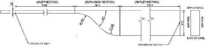
Figure 1: Asymmetric Diffuser
The boundary condition of this diffuser flow study was fixed accordingly, as shown in Figure 1. The free stream velocity and the temperature were extracted according to experiments is U∞= 10 m/s and T = 31◦ C, respectively.
Thus, the turbulent boundary layer with Re ≈ 1.1x10⁶has been anticipated. While, the dynamic viscosity and the density were extracted asµ1.8656x10⁻⁵kg/ (m.s) andρ= 1.13278 kg/m3. The turbulence intensity (Ti) =1% and the length scale (l) = 0.010 m have been defined accordingly. The only single VG model was considered in this simulation. Therefore width of the test section was reduced to half of the distance of the VGs pair (D/2) and the sidewall effect was eliminated by using symmetry boundary condition. The fully structured meshing was generated
on clean diffuser by using GAMBIT™. For controlled cased application, the hybrid mesh was used as shown in Figure 2. In order to ensure the turbulence model is capable to capture the turbulence effect near to wall bounded, the first distant node has been calculated based on y+≈ 1. The distance was calculated so that y =3.8x10⁻⁵. The mesh node distribution was same as finalized in 2D domain. The final computational volume consist about 2.5 million elements and mesh quality is not disregarded for all volume mesh.
Figure 2: Hybrid Mesh
Figure 3: Velocity Profile Base of Two Dimensional Meshes
3. Results and Discussions
3.1. Uncontrolled case
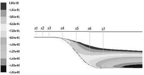
The uncontrolled case has been performed in clean diffuser and measurements were taken at seven locations on the streamwise position at x1= 1830 mm, x2= 1865 mm, x3= 1900 mm, x4= 1975 mm, x5= 2050 mm, x6= 2125 mm and x7= 2200 mm respectively. Figure 4 and 5 show the reversal flow was detected at the station x4 in both simulation and experimental result. Nevertheless, at the middle of inclined wall, the simulation was hardly to capture the exact profile as same as the experimental result. The separation point was predicted at a position about 1950 mm with 1.5% error to the experimental result. It was noted that the SST k-was slightly over predict as mentioned by previous researcher [1].
Figure 4: Velocity profile of uncontrolled case
3.2. Controlled Cases
The VG performance of diffuser flow was studied by varying its parameters such as VGs height, lateral spacing and VGs position toward the separation point as shown in Table 1. The VG was modelled in triangular shape and arranged in counter rotating position as mentioned by Godard et al. [4]. The angle of incidence,β=18◦ was fixed based on recommendation by Pauley et al. [7]. Finally, the VGs performance of the separated flow can be evaluated qualitatively and quantitatively by plotting velocity profile and contour respectively.
Table 1: VG configuration
h c d D (∆Xg)/h
S1 2 5 5 24 35
S2 4 10 10 48 22.5
S3 4 10 10 24 22.5
S4 4 10 10 24 7.5
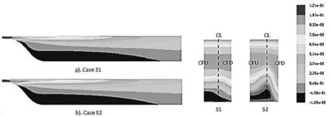
3.2.1. Case S1 & S2 (Effect of VG height)
The effect of VG height shows the separation point at station x4 was improved significantly as shown in Figure 6, when VG height was set double up from case S1. Figure 7 shows three dimensional effect of the VG height at three regions namely, common flow down (CFD), common flow up (CFU) and behind the VGs trail so called center (CL) at plane x4. One can see when VG height was fixed about 40% of boundary layer thickness (case S2) the reversal velocity region (dark) decrease tremendously especially in CFD region. While the streamwise velocity contour in Figure 7 indicated the separation point was delayed but the separation length was maintained.
Figure 6: Velocity profile of case S1 and S2 at Common Flow Down Region
Figure 7: Streamwise Velocity Contour (left) and vortex induced effect at plane x4 (right) of case S1 and S2
3.2.2. Case S2 and S3 (Effect of Lateral Spacing Ratio)
main stream velocity and boundary layer velocity was improved significantly when the lateral spacing ratio was reduced to 2.4.
Figure 8: Velocity profile of case S2 and S3 at Common Flow Down Region
Figure 9: Streamwise Velocity Contour (left) and vortex induced effect at plane x4 (right) of case S2 and S3
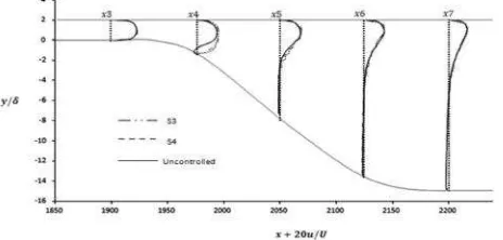
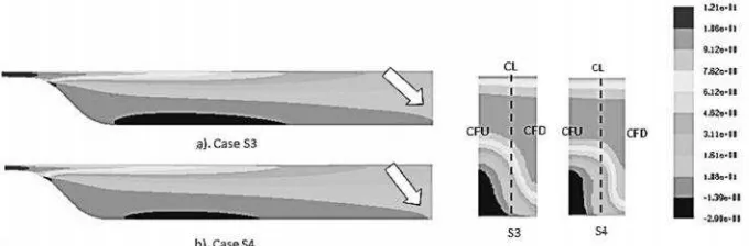
3.2.3. Case S3 & S4 (Effect of VG position)
Figure 10 and 11 shows the vortex velocity with reflect to the VGs position. It was understood that vortex strength depended on the mean flow velocity. In controlled case S4, the vortex received sufficient energy from the mean flow and improved the reversal velocity when the VG was placed close to incline wall. One can see the dark region in S4 is diminishing slowly when compare to the region in S3 as shown in Figure 11. This result shows good agreement with the finding by Valte [8]. The streamwise velocity contour for both cases indicates the VG position is capable to influence the mean flow about to reduce the separation length rather than separation point.
Figure 11: Streamwise Velocity Contour (left) and vortex induced effect at plane x4 (right) of case S3 and S4
4
Conclusions
The performance of the passive vortex generator on separated flow diffuser was successfully simulated by using the CFD code Fluent 6.3™. In the meanwhile, the turbulence separation at an extreme wall angle of 45◦ has been predicted by SST k-turbulence model. The velocity profile result of clean diffuser was shown well agreement to experimental study.
In this work, the VG performance is mostly influenced by the effect the VG height. It is identified that the VG height of 40% boundary layer thickness is capable to delay the separation point significantly. In the meanwhile the lateral spacing ratio and VG position shows positive result toward improving the reversal velocity amount in the flow domain. Again, these parameters also provide strong correlation in reducing the separation length. The performance of the flow diffuser can be enhanced by using a low ratio of lateral spacing and placed the VG closest to separation point.
In overall, the optimal VGs configuration as provide in controlled case S4 shows the best result but limited to the number parameters that have been used. Further study is required to verify the correlation of each parameter toward the separation point as well the separation length.
Acknowledgement:
The authors thank Universiti Teknikal Malaysia Melaka and Ministry of Higher Education Malaysia for sponsor the Skim Latihan Akademik Bumiputera (SLAB) of Master Innovation and Engineering Design research project.References
1. E. M. Cherry, G. Iaccarino, C. J. Elkins AND J. K. Eaton. 2006. Separated flow in a three-dimensional diffuser:preliminary validation. Center for Turbulence Research, Annual Research Brief 2006, pp.31-40 2. Lin, J.C. 1999. Control of turbulent boundary layer separation using micro-vortex generators. AIAA Paper,
99-3404
3. A. Gross, R. Jacobi and H.Fasel. 2010. Investigation of Three-Dimensional Internal and External Flow Separation. DoD High Performance Computing Modernization Program Users Group Conference
4. Godard, G. and Stanislas, M. 2006. Control of a decelerating boundary layer. Part 1: Optimization of passive vortex generators. Aerospace Science and Technology 10 181–191
5. K. A. Ahmad. 2011. Numerical Study on Effect of Reduced Frequency on a Vortex Induced by an Oscillating Sub Boundary Layer Vortex Generator. International Journal of Mechanical and Materials Engineering (IJMME), Vol.6 (2011), No.3, 317-325.
6. Serakawi, A.R. and Ahmad, K.A. 2012. Experimental study of half delta wing vortex generator for flow separation control. Journal of Aircraft vol.49, no. 1
7. Pauley, R.W., and Eaton, J.K. 1987. Experimental study of the development of longitudinal vortex pairs
embedded in a turbulent boundary layer’, AIAA Journal Paper 87-1309, Volume 26, No. 7, AIAA 19th Fluid Dynamics, Plasma Dynamics, and Laser Conference, June 8-10 1987, Honolulu, HI, p. 816-823 8. Valte, C.M. 2009. Characterization of vortex generator induced flow, PhD Thesis, Technical University of