OPTICAL SOLITON IN LONG HAUL TELECOMMUNICATIONS WITH FIBER LOSS FACTOR
Abdul Hafiz bin Mohd Tamezer
“ I hereby declare that I have read through this report entitle “Optical Solitons in long haul telecommunications with fiber loss factor” and found that it has comply the partial fulfillment for awarding the degree of Bachelor of Electrical Engineering (power electronic and drive)”
Signature : ...
Supervisor’s Name : Mr. Loi Wei Sen
OPTICAL SOLITONS IN LONG HAUL TELECOMMUNICATION WITH FIBER LOSS FACTOR
ABDUL HAFIZ BIN MOHD TAMEZER
A report submitted in partial fulfillment of the requirement for the degree of Power Electronic and Drive
Faculty of Electrical Engineering
UNIVERSITI TEKNIKAL MALAYSIA MELAKA
I declare that this report entitle “Optical Solitons in long haul telecommunications with fiber loss factor” is the result of my own research exceptas cited in the references. The report has not been accepted for any degree and is notconcurrently submitted in candidature of any other degree.
Signature : ...
Name : Abdul Hafiz bin MohdTamezer
ACKNOWLEDGEMENT
First and foremost, many thanks to Allah SWT for blessing me with good health and lots of patience in completing this project. My greatest appreciations and thank you to my supervisor, Mr. Loi Wei Sen for guiding, supervising and advising me to complete this final year project with successfully. Without his continued support and interest, this project would not have been same as presented here.
My deepest gratitude goes to two most important people who always given their loves and support, Father and mother, thank you will never seems enough to depict my appreciation. For the generous assistance in implementing various experiments, I would like to acknowledge my course mates and especially to my house mates. Thanks for all the times spent and the never ending patience. I really owe this to you guys.
ABSTRACT
ABSTRAK
TABLE OF CONTENTS
CHAPTER TITLE PAGE
ACKNOWLEDGEMENTS ii
ABSTRACT iii
TABLE OF CONTENT v
LIST OF FIGURES viii
LIST OF SYMBOLS AND ABBREVIATIONS x
1 INTRODUCTION 1
1.1 Introduction 1
1.2 Problem Statement 3
1.3 Objectives 3
1.4 Scopes 4
1.5 Methodology 4
1.5.1 Flow Chart of Overall Project 5
1.6 Outline of Thesis 6
2 LITERATURE REVIEW 7
2.1 Optical Soltions 7
2.2 Types of Solitons 8
2.2.2 Temporal Solitons 8
2.3 Optical Fiber Communications 8
2.3.1 Classification of Fiber Optic Communications 9
2.3.1.1 Multimode Step Index Fiber 10
2.3.1.2 Multimode Gradient index Fiber 11
2.3.1.3 Single Mode Step Index Fiber 12
2.4 Self Phase Modulation 13
2.5 Group Velocity Dispersion 15
2.6 Component used in Optical Fiber Communications 15
2.6.1 Optical Transmitter 15
2.6.2 Optical Receiver 15
2.6.3 Optical Filters 16
2.7 Fiber Loss 17
3 OPTICAL SOLITON SIMULATION 19
3.1 Introduction 19
3.2 Project Overview for Electrical Model 20
3.3 OptiSystem Software 22
3.3.1 Step to Create the Simulation of OptiSystem
Software 22
3.4 Project Overview for Mathematical Model 25
4.1 Electrical Model 29
4.1.1 OptiSystem Software 29
4.1.2 Experimental Setup 30
4.1.2.1 First Order Soliton 32
4.1.3 Effect of Fiber Loss 35
4.1.3.1 Fiber Loss in Optisystem 36
4.2 Mathematical Model 37
4.2.1 Numerical Solution of Nonlinear Schrödinger
Equation 37
4.2.2 Numerical Solutions for Forced Nonlinear
Schrödinger Equations (fNLS) 40
4.3 Comparison between Electrical Model and
Mathematical Model 42
4.4 Comparison between Electrical Model and
Mathematical With Fiber Loss Factor 46
5 CONCLUSION AND RECOMMENDATION 50
6.1 Conclusion 50
6.2 Recommendation 51
REFERENCES 52
LIST OF FIGURES
FIGURE TITLE PAGE
1.1 Light Travels through Optical Fiber by Totally Reflecting
from opposite wall 2
1.2 Flow Chart of Overall Project 5
2.1 Multimode Step Index Fibre 10
2.2 Multimode Gradient IndexFibre 11
2.3 single Mode Step Index Fibre 12
2.4 Instantaneous Frequency of an Initially Unchirped Pulse which has
Experienced SPM. The Central Part of the Pulse Exhibits an Up-Chirp 13
2.5 Variation of Refractive Index and Group Index with Wavelength 17
3.1 Flow Chart of Electrical Model 20
3.2 Various Components from the Component Library 22
3.3 Layouts for Component Search 23
3.4 Layouts for Optical Sech pulse Generator Properties 23
3.5 Layouts for Simulation Run 24
3.6 Signal Pulse of Optical Solitons 24
3.7 Flow Chart of Mathematical Model 25
4.1 First Order Soliton Experimental Setup 30
4.2 Graphs of First-Order Soliton Over One Period ( ) 32
4.3 Graphs of First-Order Soliton at Half Period 32
4.4 Three Dimensional Graphs of First-Order Solitons Over One Period 33
4.5 Graphical Output for First Order Soliton with a Loss of 0.35dB/km where
(a)z= 0km (b)z=12km (c)z=21km (d)z=30km 36
4.6 Graphical Output for Mathematical Model 38
4.7 Three Dimensional Graph for Mathematical Model 39
4.8 Graphical Output for Mathematical Model with Fiber Loss 41
4.9 Graphical Output at z=0 (a) Electrical model (b) Mathematical model 42
4.10 Graphical Output at z=10 (a) Electrical model (b) Mathematical model 42
4.11 Graphical Output at z=20 (a) Electrical model (b) Mathematical model 43
4.12 Graphical Output at z=30 (a) Electrical model (b) Mathematical model 43
4.13 Graphical Output at z=0 (a) Electrical model (b) Mathematical model 46
4.14 Graphical Output at z=12 (a) Electrical model (b) Mathematical model 46
4.15 Graphical Output at z=21 (a) Electrical model (b) Mathematical model 47
LIST OF SYMBOLS AND ABBREVIATIONS
GVD Group Velocity Dispersion
SPM Self-Phase Modulation
FWHM Full width at half maximum
Km Kilometers
NLS Nonlinear Schrödinger equations
CHAPTER 1
INTRODUCTION
1.1 Introduction
Nowadays, internet usage has led to high demand for communication services with unprecedented amounts of information transferred over a part to another a part of the earth. As a result, it will require higher transmission rates- especially with the delivery of audio and video files. For example, in an effort to remain competitive, internet providers always need to increase their bit rate of the amount of data they can send per second. Unfortunately, the old analog devices that carry information along copper cables using the electron is now facing great difficulties in responding to the huge demand for information. This is mainly due to the fact that they are too slow and too noisy compared to the fiber optic system. Indeed, optical digital systems can achieve higher bit rates of electronic devices and they can be cheaper in the near future.
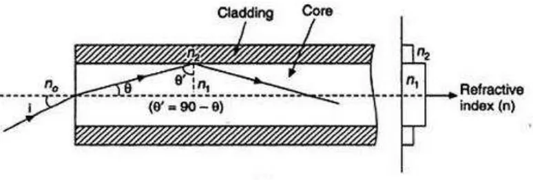
Like any other communication systems, fiber optic system consists of transmitter, receiver and transmission medium is fiber optics here. A fibre usually consists of a central part called the core (whose refractive index is ) and a peripheral part known as the cladding (whose index is ). This emitter is a laser light pulse is injected into the fiber. If we inject light properly into the fiber, the light can be guided through without having to leave the core. After propagating along the fiber, optic signals into electrical signals from the receiver to recover the initial message.
the core is greater than the cladding refractive index; critical angle of incidence does not exist. When light travels from one medium to another, lower refractive index, there is a critical angle of incidence under the really light will reflect back into the first medium to light does not penetrate the interface.
Figure 1.1 Light travels through optical fiber by totally reflecting from opposite wall
Total capacity of fiber that can be delivered is a key factor in determining performance. Due to the encoded data in a series of light pulses, a better delivery rate can be achieved by increasing the number of pulses transmitted in one second. The higher the number of pulses transmitted in one second, better delivery rate. This can be done by reducing the duration of light pulses: a short pulse, the higher the bit rate. For that purpose, some physicists now work on femtosecond laser that can produce ultra-short light pulses. Currently, the shortest laser pulses that we are capable of generating have a time width almost equal to 4 fs (4×10-15 s).
discovered first and they are often simply referred as "solitons" in optics.
1.2 Problem Statement
Huge amount of data is transfer though a small, narrow glass cable. The data will convert to the signal before it’s transmitting as optical pulses in tiny glass cable-optical fiber. Initially, huge of amount data is transferred through a small, narrow glass cable. The pulse travel in the cable is like waveguide propagation. There have a idea of the optical pulses travel in optical fiber,i.e. normal laser or renovation idea with use of solitons is a very narrow pulse with high peak power. The soliton pulses are in the stable shape and velocity is preserved while travelling along the medium. This means that solitons pulses do not spread in optical fiber after thousands of kilometers. In an optical fiber solitons pulses are generated by counter balancing the effect of the dispersion by the self-phase modulation. It is greatly interest area of new era of commutations in this century. In fact, it is quite impossible to experiment this project into hardware due to high costing and difficult to find the material in this country. However we still can explore the characteristic using OptiSystem that is suitable to find the simulation of the optical soliton.
1.3 Objectives
The project is aimed to meet the following objectives:
1) To simulate the optical solitons propagation with fiber loss in optical solitons problem 2) To investigate the effect of the fiber loss to signal propagation
1.4 Scopes
In this research, the problem is limited to find the wave propagation using OptiSystem software. The OptiSystem is used to simulate the block diagram of optical solitons and analyze result for long haul telecommunication with fiber loss factor. Due to this project which is used in long haul telecommunication, the single-mode fiber-optic cable will be used because it is provides much better performance with lower attenuation and it is suitable to used in long distance communications.
1.5 Methodology
The studies of the literature review are an important part of starting the research. Therefore, this research is beginning with a review of the literature for optical solitons in long haul communications with fiber loss factor and its application in optical fiber. The collection of information is in hard copy, such as books journals and softcopy like online journal like IEEE in PDF format and also some literature review website. The information was collected through the databases of UTeM library and internet.
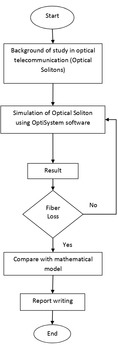
The simulation of the optical solitons propagation will be start using OptiSystem software. After the results of the simulations were obtained, the simulation with fiber loss factor will be start using the same software.
Figure1.2: Flow Chart of Overall Project Start
Background of study in optical telecommunication (Optical
Solitons)
Compare with mathematical model
End Fiber
Loss
No
Yes Simulation of Optical Soliton
using OptiSystem software
Result
1.6 Outline of Thesis
CHAPTER 2
LITERATURE REVIEW
2.1 Optical Solitons
A fascinating manifestation of the nonlinear optical fibers occurs through soliton, which is formed as a result of the interaction between dispersion and nonlinear effects. Soliton word that refers to a special type of wave packets can propagate undistorted over long distances. Solitons have been found in many branches of physics. In the context of optical fibers, solitons are not only fundamental interest but they also found practical applications in the field of fiber-optic communication. It describes the nonlinear pulse propagation on dispersive fiber-optical fibres such as self-phase modulation (SPM) and group velocity dispersion (GVD).
Optical solitons can be defined as a stable non-linear pulse of light formed in an optical fiber, which has the ability to maintain its shape and width (amplitude) as well as its phase in the presence of dispersion. This attribute is due to an effective cancellation between the dispersion effect and the nonlinear effect.
2.2 Types of Solitons
There are two main kinds of optical solitons.
2.2.1 Spatial Solitons:
The nonlinear effect can balance the diffraction. The electromagnetic field can change the refractive index of the medium while propagating, thus creating a structure similar to a graded index fiber. If the field is also a propagating mode of the guide it has created, then it will remain confined and it will propagate without changing its shape
2.2.2 Temporal Solitons:
For nonlinear optics, there are two main kinds of optical solitons which is temporal solitons and spatial solitons. Soliton wave is realized in many different physical situations, ranging from the mechanical movement of light propagation [5]. In general, they are strong disturbances, which can transmit distortion free for quite a long distance. The strength of optical solitons can be shown in the time domain (temporal solitons), the horizontal space (solitons space), or both (light bullets). Time has been extensively studied Solitons in optical fibers for a great utility in long distance optical communications. They exist as a result of the dissemination of the balance between the competing effects of linear refractive index and nonlinear phase modulation.
2.3 Optical fiber communications
(light wave communication) has the advantages, the most important are:
The capacity of the fiber for transmission of data: a single silica fiber can carry hundreds of thousands of telephone lines; only use a small part of theoretical capacity. In 30 years, progress in respect of the transmission capacity of fiber links has been significantly faster than for example, advances in computer speed or storage capacity.
The losses for light propagating in fibers are amazingly small: ≈0.2 dB/km for modern single-mode silica fibers, so that many tens of kilometers can be bridged without amplifying the signals.
A large number of channels can be reamplified in a single fiber amplifier, if required for very large transmission distances.
Due to the large transmission rate is achieved; the cost per bit transported may be too low.
Compared with electrical cables, fiber optic cable is very light, so that the cost of installing fiber optic cables can be much lower.
Fiber optic cable immune to the problems that arise with electric cables, such as ground loops or electromagnetic interference (EMI).
2.3.1 Classification of Fiber Optic Communications
The fiber optic communication can be divided into three modes.
2.3.1.1 Multimode Step Index Fiber
Step index multimode was the first fiber design but is too slow for most uses, due to the dispersion caused by the different path lengths of the various modes. Multimode fibres carry many modes of different phase and group velocities. The difference in group velocities of the different modes causes spreading of the temporal envelopes of the individual pulse-excited modes and thus cannot maintain high bit-rate pulse streams(short pulses) over large distances (several kilometers).
Due to its large core, some of the light rays that make up the digital pulse may travel a direct route, whereas others zigzag as they bounce off the cladding. These alternate paths cause the different groups of light rays, referred to as modes, to arrive separately at the receiving point.
The pulse, an aggregate of different modes, begins to spread out, losing its well-defined shape. The need to leave spacing between pulses to prevent overlapping limits the amount of information that can be sent. This type of fiber is best suited for transmission over short distances.