Abstract— This project is to design and develop a multi-input algorithm of sensors for Autonomous Underwater Vehicle (AUV) applications which is having high performance automated detection and monitoring on underwater application or for surveillances and defense application. The monitoring and detection will be based on multi-input received from the intelligent and active vision and sensors implemented in the AUV. The sensors implemented in AUV such as vision system, hydrophone system and sonar system. The new design of vision system for AUV with the implementation of wireless camera, whereby, produce clearer image. The ultrasonic sensor is a main device to transmit and receive the signal from the obstacle. The ultrasonic sensor will be combined to the ultrasonic circuit. Hydrophone is an underwater microphone which with the help of pressure impulses of acoustic waves converts them into electrical signals which in further are used for communication. It was designed to be used underwater for recording or listening to underwater sound.
Keywords: AUV, Vision, Sonar, Hydrophone.
I. INTRODUCTION
n Autonomous Underwater Vehicles (AUV) is very challenging research area and valued for both their expand ability and replace ability because they can be deployed in hazardous environments without risking human divers. This emerging field is very economical as AUVs has the potential for cheap scalability makes it ideal for large scale and long term data collection tasks. An AUV is a robotic device that is driven through the water by a propulsion system, controlled and piloted by an onboard computer, and maneuverable in three dimensions [1],[2]. This level of control, under most environmental conditions, permits the vehicle to follow precise preprogrammed trajectories wherever and whenever required [3],[4],[5].
Sensors on board the AUV sample the ocean as the AUV moves through it, providing the ability to make both spatial and time series measurements [6]. Sensor data collected by an AUV is automatically geospatially and temporally referenced and normally of superior quality [7]. The sensors implemented in AUV such as vision system, hydrophone system and sonar system. In this paper will describe for the sensor that mention such as vision, sonar and hydrophone sensor.
II. GENERAL DESIGN OF AN AUV
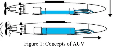
There are several aspects in AUV electrical and mechanical design need to be looked at closely so that the design will be successful. In order to design any underwater vehicle AUV, it is essential or compulsory to have strong background knowledge, fundamental concepts and theory about the processes and physical laws governing the underwater vehicle in its environment. Therefore, the major design aspects that need to be considered [8],[9],[10] are identifying hull design, propulsion, submerging and electric power. Figure 1 is the method that we are using to design an AUV.
Figure 1: Concepts of AUV
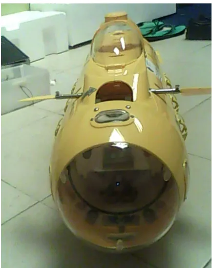
Figure 2, 3 and 4 shows the real AUV for this project that will be attached with multi-input sensors system.
DESIGN AND DEVELOPMENT OF MULTI-INPUT SENSOR ALGORITHM FOR
AUTONOMOUS UNDERWATER VEHICLE (AUV) APPLICATIONS
MOHD SHAHRIEEL MOHD ARAS, MUHAMMAD HERMAN BIN JAMALUDDIN, HYREIL ANUAR BIN KASDIRIN
Mechatronics Department, Faculty of Electrical Engineering, Universiti Teknikal Malaysia Melaka
Figure 2: An AUV (top view)
Figure 3: An AUV (side view)
Figure 4: An AUV (front view) III. DESIGN PROCESS
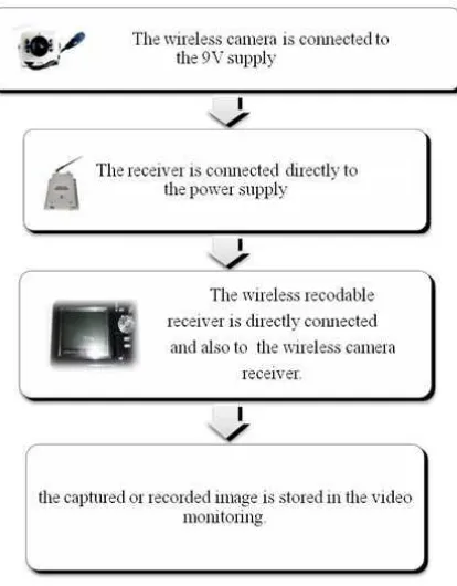
Figure 5: Process to set up the equipments
Analysis is done for this particular project as to prove the ability of this new vision system either it can view the clearer image or not. The main purpose of this analysis is to captured clear image that had been submerge in the water.
B-Hydrophone system
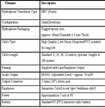
The hydrophone have many advantages such as dielectric substance, contain in shielded, provides a broadband and highly sensitive to underwater sound vibrations. Because of that reason, the Dolphin Ear DE2000 Series Hydrophone is applied in this project. Figure 6 shows the Dolphin Ear DE2000 Series Hydrophone and their specification as shown in Table 1.0.
TABLE 1.
SPECIFICATION OF DOLPHIN EAR DE 2000 HYDROPHONE
C- Sonar system
Ultrasonic is sound with frequencies above 20 kHz. Since the sensor that use in this project is at 40 kHz, they are definitely ultrasonic and not audible [11]. Before start the project, it necessary to know the basic of the operation the hardware or the software. The main hardware that needed in this project is ultrasonic sensor while the software that need is this project is mikroC function as a compiler. Basically, the microcontroller tells the ultrasonic sensor to go. Then, ultrasonic sensor emits a mostly inaudible sound; time passes, and then detects the return echo [12],[13]. It then immediately send a voltage signal to the microcontroller, which by keeping track of the time that passes and calculate the distance of the objects detected. Figure 7 shows the connection of the hardware that involved in this project development.
Figure 7: The connection of the hardware
IV. RESULT
TABLE 2. environment might yield different result for determining the appropriate distance for producing clearer underwater images as shown in Figure 8.
Figure 8: Performance versus distance for three different types of water.
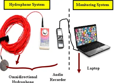
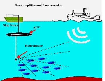
Figure 9 shows the hydrophone system for AUV which are hydrophone and monitoring. The sound signals will be obtain by placing the Omni directional hydrophone into underwater [15],[16]. After that, the sound signals are recorded by voice recorder and save the digital recording into hard disk of laptop or computer. Then, the sound signal is analyzed by using Spectrogram software. After that, the system is applied to the Autonomous Underwater Vehicle as shown in Figure 10.
Figure 10: Applying the Hydrophone System to AUV
The hydrophone system is tested and applied in order to make sure there is in good condition. Therefore, the hydrophone system is tested in Rumah Akuarium, Taman Botanikal, Air Keroh Melaka. The underwater species are Puyu,
Lampam Sungai, Krai, Silver Dollar, Kelah, Baro Brad Oscar, Sebarau, Tortoise, Tiger Borb, Kalai, and Patin. Figure 11
shows the Spectrogram of Tortoise.
Figure 11: Spectrogram of Tortoise
Figure 12: Spectrogram for Passive Area
Figure 12 shows the spectrogram for an underwater in passive condition. After that, data will be use to provide the sampling rate of underwater species in details.
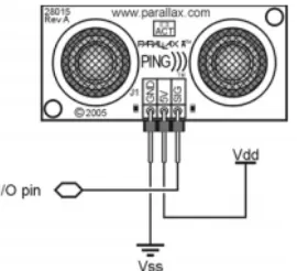
Figure 13 shows the PING Ultrasonic Sensor Distance circuit. The PING sensor has a male 3-pin header that function used to supply ground, power and signal. The header may be plugged into a directly into solderless breadboard, or into a standard 3-wire extension cable [17]. Refer to the Figure 14 shows the pin definition of PING ultrasonic distance sensor circuit. Table 3 refers the pin definitions of the circuit.
Boat amplifier and data recorder
Figure 13: PING Ultrasonic Sensor Distance
Figure 14: Pin Definition of PING Ultrasonic Distance TABLE 3.
PIN DEFINITIONS
GND Ground (Vss)
5V 5 VDC (Vdd)
SIG Signal (I/O pin)
A. Developed a Controller Board and Ultrasonic Distance Circuit
Based on the project, the controller board for PIC16F877A is developed. The board is divided into 2 sections which are; the burner section and the controller section. All the distance that detected by the ultrasonic sensor will be displayed on the 2x16 LCD that already attached to the microcontroller board. The size of this board is about; 10cm X 30 cm. Figure 15 shows the circuit of controller board.
Figure 15: Circuit of controller board.
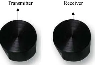
Then, the microcontroller part will be combined with the ultrasonic distance sensor circuit. The ultrasonic sensor will be replaced with the proowave ultrasonic TXR sensor. Figure 16 shows the proowave ultrasonic TXR sensor.
Figure 16: Proowave Ultrasonic TXR
V. CONCLUSION
New design of vision system with the implementation of the wireless camera as the vision system is successfully. It has found that this new design of vision system had improved slightly of the quality of the submarine image that being captured. However, there are still the limitation regarding to capturing underwater images due to a difference density between marine environment and ground environment
.
The hydrophone tested in excellent condition, so it proven by developed the hydrophone system. The hydrophone system is including of process to record the underwater sound. Then, the underwater sound is simulated into sampling rate frequency to produce the data bank of underwater sound in Malaysia. It also can be used for testing and learning conventional and advanced control algorithms and techniques to other underwater systems.
With a limited budget a small autonomous underwater vehicle has been developed. The mechanical structure is produced. Future development and improvement with show that this compared to other AUV projects, smaller and cheaper concept will succeed.
ACKNOWLEDGEMENTS
We wish to express our gratitude to honorable University (Universiti Teknikal Malaysia Melaka) especially to higher management for give the financial as well as moral support. And also would like to thank CRIM because their tolerance for complete this project successfully.
REFERENCES
[1] L.A. Gonzalez, “Design, Modelling and Control of an Autonomous Underwater Vehicle,” Bachelor of Engineering Honours Thesis, the University of Western Australia, 2004.
[2] E. H. Rögnvaldsson, “ Development of an Inexpensive Experimental Autonomous Submarine,” Master Thesis in Computer Systems Engineering, University of Southern Denmark, Odense.
[3] S.Hsu, C.Mailey, C. Montgomery, R.Moody, “ Autonomous Underwater Vehicle— “Camera” ,” Duke & NC state university.
[4] Bernhard G. ,”Development of an Autonomous Underwater Vehicle in an Interdisciplinary Contex,” Diploma Thesis The University of Western Australia, 2006.
[5] H.Clarke, E.Crewshaw et. al., “ Design and Development of the AUV Harp”, Department of Ocean Engineering Florida Atlantic University [6] Gonzalez, R. C., & Woods,R. E. (2002). Image Compression. Digital Image processing (pp. 420). New Jersey: Prentice Hall.
[7] Huat Lim D. L. (2004, November 1). Definition of Autonomous Underwater Vehicle. Design of Vision System for Autonomous Underwater Vehicle.
[8] Raynolds J. (1998, October). Problem of Underwater Vision. Autonomous Underwater Vehicle: Vision System.
[9] Wireless Camera. (n.d). OmniVision CMOS (Silver). Retrieved January 5, 2009, from
http://www.geeks.com/details.asp?invtid=CM208CA&cat=VID
[10] Wireless.(n.d.).Concept of Wireless. Retrieved October 8, 2008, from http://en.wikipedia. org/wiki/Wireless [11] Underwater_acoustics. Retrieved on October 2009 from
[12] http://en.wikipedia.org/wiki/Underwater_acoustics
[13] C. von Alt, “Autonomous Underwater Vehicles Prepared for the Autonomous Underwater Lagrangian Platforms and Sensors Workshop,” Woods Hole Oceanographic Institution March 24-26, 2003
[14] Autonomous Underwater Vehicle. Retrieved on September 2009 from http://en.wikipedia.org/wiki/Autonomous_underwater_vehicle [15] Hydrophone. Retrieved on September 2009 from
[16] http://en.wikipedia.org/wiki/Hydrophone
[17] Underwater_acoustics. Retrieved on October 2009 from http://en.wikipedia.org/wiki/Underwater_acoustics
[18] Appendix C, “Underwater Sound Concepts”, Undersea Warfare Training Range, C1-C13.[online], 2009. Available: http://projects.earthtech.com/uswtr/EIS/FOEIS-EIS_2009/FOEIS-EIS_2009.htm