UNIVERSITI TEKNIKAL MALAYSIA MELAKA
DESIGN AND DEVELOPMENT ROBOT DRIVE SYSTEM USING
MECANUM WHEEL
This report submitted in accordance with requirement of the Universiti Teknikal
Malaysia Melaka (UTeM) for the Bachelor Degree of Manufacturing Engineering
(Robotic and Automation) with Honours.
by
ZUL AZRI BIN ZAINAL B050810123
FACULTY OF MANUFACTURING ENGINEERING
UNIVERSITI TEKNIKAL MALAYSIA MELAKA
BORANG PENGESAHAN STATUS LAPORAN PROJEK SARJANA MUDA
TAJUK: Design and development robot drive system using Mecanum Wheel
SESI PENGAJIAN: 2010/11 Semester 2
Saya ZUL AZRI BIN ZAINAL
mengaku membenarkan Laporan PSM ini disimpan di Perpustakaan Universiti Teknikal Malaysia Melaka (UTeM) dengan syarat-syarat kegunaan seperti berikut:
1. Laporan PSM adalah hak milik Universiti Teknikal Malaysia Melaka dan penulis. 2. Perpustakaan Universiti Teknikal Malaysia Melaka dibenarkan membuat salinan
untuk tujuan pengajian sahaja dengan izin penulis.
3. Perpustakaan dibenarkan membuat salinan laporan PSM ini sebagai bahan pertukaran antara institusi pengajian tinggi. atau kepentingan Malaysia yang termaktub di dalam AKTA RAHSIA RASMI 1972)
DECLARATION
I hereby, declared this report entitled “Design and development a robot drive system using mecanum wheel” is the results of my own research except as cited in references.
Signature : ………..
Author’s Name : ZUL AZRI BIN ZAINAL
APPROVAL
This report is submitted to the Faculty of Manufacturing Engineering of UTeM as a
partial fulfillment of the requirements for the degree of Bachelor of Manufacturing
Engineering (Robotic and Automation) with Honours. The member of the supervisory
committee is as follow:
i
ABSTRAK
Pemilihan penggerak untuk robot saat ini masih tertumpu kepada penggunaan roda
biasa. Hal ini mungkin kerana kosnya yang jauh lebih murah berbanding dengan roda
mecanum. Projek ini akan menunjukkan manfaat dan kemampuan robot apabila
menggunakan roda mecanum sebagai penggerak dari segi jenis gerakannya. Roda
Mecanum juga dikenali sebagai Roda Sweden yang telah wujud di dunia sejak tahun
1973. Roda mecanum adalah istimewa dan unik jika dibandingkan dengan roda lain
tetapi roda ini mahal berbanding dengan roda standard yang lain dan kerana
rekabentuknya, proses pengaturcaraan lebih sukar dan rumit. Tujuan projek ini adalah
untuk merancang dan mengembangkan sebuah robot yang mampu bergerak di segala
arah dengan menggunakan roda mecanum khusus. Projek ini melibatkan proses untuk
mereka bentuk dan membina sistem pandu robot dengan roda mecanum dan
dikendalikan secara manual menggunakan alat kawalan jauh. Pada peringkat awal projek
ini di PSM1, ia melibatkan proses untuk merancang dan membina robot dari segi
struktur mekanikal, litar elektronik dan pengaturcaraan PIC. Dua rekabentuk konsep
telah dicadangkan. Yang terbaik dipilih untuk fabrikasi. Projek ini melibatkan proses
untuk menghasilkan alat kawalan jauh khas untuk robot dan ‘voltage regulator’ dalam
proses fabrikasi komponen elektronik. Komponen SK40C dan MD30B, juga gunakan
dalam projek ini sebagai mikropemproses dan pemacu motor. Setelah semua proses
selesai termasuk pemasangan semua komponen, kod pengaturcaraan dimuat turub dan
juga di uji. Kaedah ujian dirancang dan dilaksanakan dalam menentukan samada projek
ini mencapai matlamat projek ataupun tidak. Sebagai kesimpulan, projek ini berjaya
mencapai matlamat projek tapi masih memerlukan penambahbaikan lebih lanjut di masa
ii
ABSTRACT
Locomotion for most mobile robots today is still focused on the standard wheel. This
may be due to its cost which is much cheaper compared to mecanum wheel. This project
will show the benefit of using mecanum wheel as locomotion from its movement
this project at PSM1, it involves a process to design and develop the robot mechanical
structure, electronic circuit and programming PIC. Two conceptual designs have been
proposed. The best one will be chosen for fabrication. This project involves to fabricate
a custom made of teach pendant and voltage regulator for electronic component. The
SK40C and MD30B, also being use in this project as the microcontroller and motor
driver respectively. After all designing and development process is fully done, it
involves to assemble and component, loading programming and test the robot. The
testing methods are planned and perform in order to define weather this project is
achieve the objective or not. As the conclusion, this project is successfully achieved the
iii
DEDICATION
This final year project report or PSM1 report is wrote in order to fulfill the requirement
before continue work for PSM2 project. First of all, this report will dedicates to beloved
supervisor, Madam Syamimi binti Shamsuddin who always giving advice and best
guides to write a best report. Without her guidance, I would be not able to write this
report with good contents and with proper format. This report also will dedicate to my
family who are always supports me to do best in study especially my mom and dad.
Finally, I would like to thanks to all of my friends especially Mohd Iskandaredzuan,
Mohd Firdaus, Mazalinda and Kannan; student under Madam Syamimi supervision for
PSM project for your support and kindness in helping me to finished this report. Thank
iv
ACKNOWLEDGEMENT
I would like express my gratitude especially to Allah S.W.T for His fate on me through
this project and chances give to me to keep breathing and healthy until today. And also
to everyone who has offered me valuable advice in order to finish this project.
First of all I would like to take this opportunity to express my sincere thanks to my
dissertation supervisor, Pn Syamimi for her valuable time on advising and guides. My
thanks are also to family who always support for my success.
ZUL AZRI BIN ZAINAL
v
1.1.3 Classification of Robot 3
vi
2.2.2.1 Application of manual mobile robot 15
2.2.2.2 Manual mobile robot teaching pendant 16
2.3 Actuator 18
2.4.2.1 Mecanum Wheel direction control 25
2.5 Robot Platform & dimension 26
2.6 Microcontroller 27
2.6.1 PIC 28
2.6.2 ATMEL AVR 30
vii
2.8.1 Software for mechanical design 35
2.8.1.1 Catia 36
2.8.1.2 AutoCAD 36
2.8.1.3 Solidwork 37
2.8.2 Software for design PIC Programming 38
2.8.2.1 Micro C 38
2.8.2.2 MPLab 39
2.8.3 Software for design circuit 39
2.8.3.1 Proteus 40
viii
2.10.1 Design and Control of Mobile Robot with Mecanum Wheels by Han et. al. 45
2.10.1.1 Project summary. 45
2.10.1.2 Introduction 46
2.10.1.3 Method 47
2.10.1.4 Project Result & Discussion 47
2.10.1.5 Project overview 49
2.10.2 Designing Omni-Directional Mobile Robot with
Mecanum Wheel by Efendi et. Al 49
2.10.2.1 Project Summary 50
2.10.2.2 Project Result and Discussion 51
2.10.2.3 Project Review 52
3.0 METHODOLOGY 53
3.1 The Overall Flowchart 53
3.2 Phase 55
3.2.1 Literature Research Stage 55
3.2.2 Design Stage 56
3.5.1 Mechanical designing software 61
3.5.2 Circuit designing software 63
3.6 Project tools and equipped 66
3.6.1 Drilling machine 66
ix
3.6.3 Band Saw Metal Cutter 66
3.7 Conclusion 67
4.0 DESIGN AND DEVELOPEMENT
4.1 Introduction 69
4.2 Mechanical Designing Stage 70
4.2.1 Conceptual Design 1 70
4.2.1.1 Advantage Of Design 1 70
4.2.1.2 Disadvantages 71
4.2.2 Conseptual Design 2 71
4.2.2.1 Advantages Of Design 2 72
4.2.2.2 Disadvantage 72
4.2.2.3 Conceptual Design 3 73
4.2.3.1 Advantages Of Design 3 73
4.2.3.2 Disadvantage 74
4.3.1 Remote Control / Teaching Pendant Circuits 75
4.3.2 Voltage Regulator Circuits 75
4.4 Programming Design Stage 76
4.5 Mechanical Development Stage 77
4.5.1 Robot Base 77
4.5.2 Wheel coupling 79
4.6 Electrical / Circuit Development Stage 80
4.6.1 Teach Pendant 81
4.6.2 Voltage Regulator 82
4.6.3 PIC Board Cytron SK40C 82
4.6.4 Motor Driver Cytron MD30B 83
x 5.0 TESTING, RESULT AND DISCUSSION
5.1 Introduction 86
5.2 Testing Stage 86
5.2.1 PIC Kit Testing and Result 87
5.2.2 Motor Testing and Result 88
5.2.3 Teach Pendant Testing and Result 89
5.2.4 Avoiding obstacle Testing and Result 91
5.2.5 Discussion 96
6.0 CONCLUSION AND SUGGESTION
6.1 Introduction 97
6.2 Conclusion 97
6.3 Suggestion 98
6.3.1 Motor Speed 98
6.3.2 Suspension 98
6.3.3 Control system 99
6.3.4 Visual Basic control 99
REFERENCES 99
xi
LIST OF TABLE
5.1 PIC kit SK40C testing sheet 86
5.2 Motor testing Check list 88
5.3 Teach Pendant Check list 89
5.4 Motor rotation formation for robot movement 90
xii
LIST OF FIGURES
1.1 Robot classification 5
1.2 Articulated robot 5
1.3 Mobile robots for hazardous task 6
1.4 Mecanum wheel variations 7
2.1 Autonomous Legged Robot 14
2.2 Toyota Motor's human-controlled walking robot 'I-foot,' 15
2.3 NASA robot in space 16
2.4 RF Remote with Thumb Joystick 17
2.5 DC Motor working principle 19
2.6 Standard Wheel 23
2.7 Omni-directional wheel 24
2.8 Wheel rotation and direction effects 26
2.9 PIC 16F877A with pin-out code 28
2.10 Rivet pin 43
2.11 Screw variations 44
2.12 Force vector created by Mecanum wheel 51
3.1 Overall flow chart for project process 54
3.2 Flow chart of the Research Stage 55
3.3 Flow Chart for Designing Stage 56
3.4 Flow Chart of the Testing and Analysis Phase 57
3.5 Example of book cover 58
3.6 An Example of Robot Base Using Aluminum 59
xiii
3.8 Wheel Mirrored Positioned at Robot Base 60
3.9 Autocad 2004 in Start Menu 61
3.10 Autocad 2004 Window appeared 62
3.11 Autocad Drawing Tools Window 62
3.12 Isis Proteus icon 63
3.13 window appear 63
3.14 click on component mode 64
3.15 click on “Pick from Library” icon 64
3.16 Pick devices 65
3.17 Save design icon 65
4.1 First Conceptual Design 70
4.2 Second Conceptual Design 71
4.3 Third Conceptual Design 73
4.4 Teach Pendant Circuit Diagram 74
4.5 Voltage Regulator 75
4.6 Robot base design using Solidwork Software 76
4.7 Mecanum Wheel Mounted On the Robot Base frame 77
4.8 Mecanum Wheel 78
4.9 Coupling 79
4.10 Left; the coupling, Right; Coupling mounted to wheel and motor’s shaft. 79
4.11 Left; Inside Teaching pendant, Right; teaching pendant outside look 80
4.12 Voltage Regulator 81
4.13 Cytron SK40C PIC Kit 82
4.14 Cytron MD30B Motor Driver 83
4.15 Final Assembly of Mecanum Wheel Robot with teach pendant 84
5.1 Cytron PIC Kit Button to LED Test 87
1
CHAPTER 1
INTRODUCTION
This chapter discusses the basic idea of this PSM project; design and development of a
robot drive system with Mecanum Wheel. The topic that will be covered in this chapter
is project background, problem statement, project aim & objective, scope, project
planning and expected outcome.
1.1 Background
Robot basically can be describe as a machine that programmable and can perform any
task without human control. Human tend to build a robot because the robot able to work
in flexible and unlimited time, able to handle heavy task and also able to repair if having
any damages or problems. According to that, robot nowadays is popular in use
especially in manufacturing and production industries. It can be prove by seeing to
Malaysian car brand companies such as Perodua and Proton that are using a robot in
2
topic then will explained more about the robot including with robot history, its definition
and many more.
robot functions and ability. After for a long time human keep build the unnamed system,
the word “Robot” then had been introduced by Czech writer, Karel Capek in his play
entitled R.U.R or in full name is Rossuum's Universal Robots in early 1920s. "Robot" in
Czech comes from the word "robota", meaning "compulsory labor" (Isom 2005). The
robot technology today’s is advance until the robot were able to walk and act as a human
and also able to serve a human. It can seen in year 1996 when Honda build the self
regulating, bipedal humanoid robot called ASIMO.
1.1.2 Robot Definition
There is lots of different definitions of robots can be seen in different dictionaries and
encyclopedias. But the basic knowledge about robot is it is manufactured by a human to
perform any human task that may harm human if performed. A robot is a
re-programmable multifunctional manipulator designed to move material, parts, or
3
of tasks (Zhihong 2006). Robot basically are built either to be control manually by a
teach pendant or autonomously controlled. Manual robot is a robot that controlled by an
operator in order to move or perform any task in certain range. The device used to
control the robot called as teach pendant. Autonomous robot is different with manual
robot as it is without human control. Autonomous robot basically will perform a task by
a programming inserted in robot memory. So that, in order to change the autonomous
robot task, human need to add or reprogram the robot.
Robotics can be described as a study of robots. In addition for this sub-title, there are
three Isaac Asimov's laws of Robotics. The laws are:-
a) A robot may not injure a human being, or, through inaction, allow a human being to
come to harm.
b) A robot must obey the orders given it by human beings except where such orders
would conflict with the First Law.
c) A robot must protect its own existence as long as such protection does not conflict
with the First or Second Law.
These three Isaac Asimov’s laws is basically is used as a guide or reference for any
human who want to built a robot. It is because Asimov believes in fictions that machine
or system able to harm and destroyed its creators and he believe that knowledge has it
dangers (Clarke 1993). Because of he’s believes, he create these 3 laws for creator
4
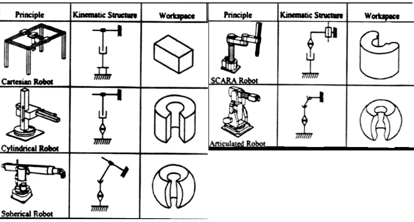
1.1.3 Classification of Robots
There are lots of robot types in this world. The main classification of robot includes;
Cartesian Robot, Parallel Robot, Spherical Robot, Scara Robot, Cylindrical Robot,
Articulated Robot and Mobile robot. Below are the definitions of every category (Types
Of Robots, ROVer Ranch)[4]:-
a) Cartesian robot /Gantry robot: Used for pick and place work, application of sealant, assembly operations, handling machine tools and arc welding. It's a robot whose arm
has three prismatic joints, whose axes are coincident with a Cartesian coordinator.
b) Cylindrical robot: Used for assembly operations, handling at machine tools, spot
welding, and handling at diecasting machines. It's a robot whose axes form a
cylindrical coordinate system.
c) Spherical/Polar robot: Used for handling at machine tools, spot welding, diecasting,
fettling machines, gas welding and arc welding. It's a robot whose axes form a polar
coordinate system.
d) SCARA robot: Used for pick and place work, application of sealant, assembly
operations and handling machine tools. It's a robot which has two parallel rotary
joints to provide compliance in a plane.
e) Articulated robot: Used for assembly operations, diecasting, fettling machines, gas
welding, arc welding and spray painting. It's a robot whose arm has at least three
5
f) Parallel robot: One use is a mobile platform handling cockpit flight simulators. It's a
robot whose arms have concurrent prismatic or rotary joints.
g) Mobile robot: have the capability to move around in their environment and are not
fixed to one physical location. Mobile robot function is flexible and it is basically
according to its creator research and focus in performing task.
Figure 1.1 below shows the figure of five robot classification listed and discussed from
seven which is; Cartesian robot, cylindrical robot, spherical robot, scara and articulated
robot. The figure is consist with it kinematic structure and working space.
Figure 1.1 Robot classification; Cartesian, cylindrical, spherical, scara and articulated robot (Braz
6
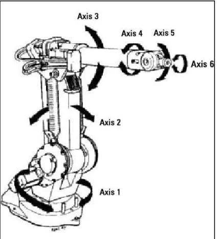
Figure 1.2 then show the image or parallel robot while 1.3 is a mobile robot.
Figure 1.2 Articulated robot (Hyland 2001).
7
1.1.4 Application of Mobile Robot
Mobile robot can be described as a small robot that operated autonomously or manually
controlled that can move at any environment profile given. Every mobile robot can be
operated to do any task depending to its function and reason of its development. Mobile
robot nowadays is widely used in order to perform any task that simple and repeated job
or dangerous to human being such as a mobile robot for military used, for an example;
the mine detection robot. Mobile robot is widely in use today in many sectors. In
manufacturing industries as an example, mobile robot can be used as a part supplier
from section to section. It will reduce manpower from supply parts and also will increase
accuracy to supplying time. Because of mobile robot size is not over than human sizes
and have capability to move around, human tend to use it as a service robot in certain
area such as shopping complex for shopping guidance and hospital for nurses and doctor
support service. Basically, mobile robot can be used in any sectors and its applications
are wide as it can be design and built according to desire task.
1.1.5 Mobile Robot with Mecanum Wheels
mecanum wheels specialty. Another specialty of using mecanum wheel is all wheels are
consists with independently motor driver and all wheels are giving its role to perfrom