UNIVERSITI TEKNIKAL MALAYSIA MELAKA
DESIGN AND FABRICATION OF A CHECKING FIXTURE FOR
A PRESS PART COMPONENT
This report submitted in accordance with requirement of the Universiti Teknikal
Malaysia Melaka (UTeM) for the Bachelor Degree of Manufacturing Engineering
(Manufacturing Design) with Honours.
by
IDRIS BIN SAARAN
i
ABSTRACT
This thesis contains the report of checking fixture design and fabrication for a press
part component; caster. The aim of this thesis is to present checking fixture for a
wheel caster. Actual measurement data of wheel caster is gathered and transform into
CAD data. Design of checking fixture and caster are made through the use of
Solidwork design software. This report consist of six chapters which is chapter one
explain about the objectives and scopes of the project, chapter two going through
about the study of checking fixture design and fabrication. Chapter three is
explaining about methodology chosen to achieve the objectives stated. Chapter four
is explaining about result of each objective while chapter five describe about
discussion of the result. Techniques of inspection are also indicated and explained.
For the chapter six, it is conclude the whole project in term of the achievement of the
objectives. This study is important to apply basis understanding of design and
ii
ABSTRAK
Tesis ini mengandungi laporan berkaitan projek rekabentuk dan pembuatan alat
untuk pemeriksaan produk yang dihasilkan melalui kerja tekan iaitu pemegang roda
untuk troli barangan. Matlamat tesis ini adalah untuk menghasilkan satu alat khusus
untuk pemeriksaan pemegang roda. Data pengukuran sebenar pemegang roda
dikumpulkan dan diubah ke dalam data CAD. Rekabentuk alat ini dan pemegang
roda dibuat menggunakan perisian rekabentuk Solidwork. Laporan ini mengandungi
enam bab dan bab satu menjelaskan mengenai objektif-objektif dan ruang lingkup
projek, bab dua menerangkan tentang kajian terhadap reka bentuk dan pembuatan
alat pemeriksaan. Bab tiga menerangkan mengenai kaedah yang dipilih untuk
mencapai matlamat-matlamat yang telah dinyatakan pada bab satu. Bab empat pula
memperincikan tentang keputusan daripada pelaksanaan projek manakala bab lima
pula membincangkan keputusan yang dicapai daripada pelaksanaan projek ini.
Teknik-teknik bagi pemeriksaan juga ditunjukkan dan dihuraikan. Kesimpulan pula
dinyatakan dalam bab enam. Kajian ini ialah penting untuk mengaplikasikan asas
iii
ACKNOWLEDGEMENTS
Dear Mum and Dad at Jelebu, Negeri Sembilan, thanks for your prayers,
blessing, and financial support. Not to forget my siblings that gives me a support when each time I’m feeling down. To all my friends, thanks a lot for sharing an idea to complete this thesis.
A special thanks and dedication to my supervisor, Mr. Wahyono Sapto
Widodo for his untiring devotion in supervision and guiding this thesis. Also for his
kindness, patient, and supporting, I wish him thanks a lot. Also to Mr. Ismail bin Abu
iv
1.3 Objectives of the Project ... 2
1.4 Scopes and Key Assumption ... 3
1.5 Importance of the Study ... 3
2.2.2.1 Locating From a Flat Surface ... 13
2.2.2.2 Locating From an Internal Diameter ... 14
v
2.2.3 Clamping and Workholding Principles ... 19
2.2.4 Types of Clamp ... 19
2.4 Computer Numerical Control (CNC) ... 35
3. METHODOLOGY ... 38
3.1 Introduction to Methodology ... 38
3.2 Execution of Project ... 40
vi
4.1 Introduction ... 41
4.2 Design of Checking Fixture ... 41
4.2.1 Caster Drawing... 41
4.3 Preparation of CNC Program ... 51
4.3.1 Converting Solidwork Part Drawing to Catia Part ... 51
4.3.2 Machining Program & Simulation ... 52
4.4 Fabrication of Checking Fixture ... 54
4.4.1 Fabrication of Fixture Body ... 54
4.4.2 Fabrication of Base Plate and Support Plate ... 55
4.4.3 Fabrication of Clamp Bracket ... 57
4.4.4 Fabrication of Clamp Bracket Stand ... 58
4.4.5 Fabrication of Pin ... 59
4.4.6 Fabrication of Fixture Body Stand ... 60
4.4.7 Fabrication of Holder ... 61
4.4.8 Assembly of Checking Fixture ... 62
4.5 Summary ... 63
5. DISCUSSION ... 64
5.1 Introduction ... 64
vii
5.3 Preparation of CNC Program ... 66
5.4 Fabrication of Checking Fixture ... 66
5.5 Method of Inspection ... 68
B Isometric View of Checking Fixture
viii
LIST OF TABLES
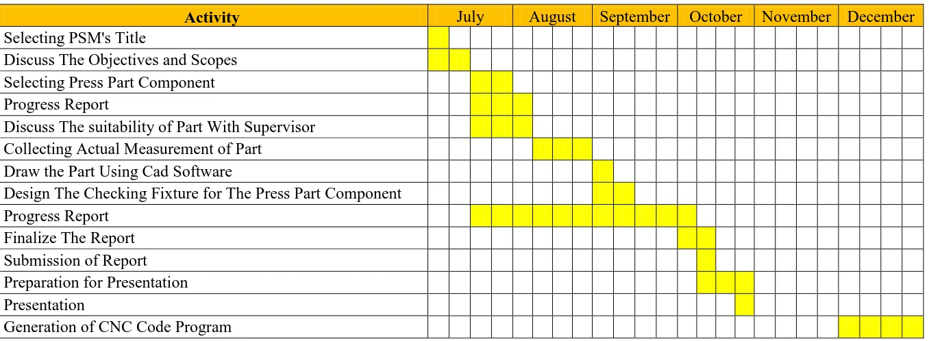
1.1 Gantt chart PSM 1 4
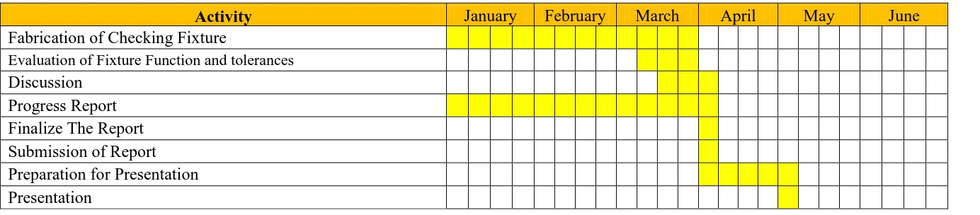
1.2 Gantt chart PSM 2 5
2.1 Elements Should Be Considered in Selection of Locator and Support 11
2.2 Clamping forces generated by screw 21
2.3 Properties of Delrin AF Blend 33
2.4 Mechanical Properties of Mild Steel 34
2.5 Mechanical Properties of Aluminum 35
2.6 Coding for Preparatory Function 37
2.7 Coding for Miscellaneous Function 37
4.1 Process Planning 53
ix
LIST OF FIGURES
2.1a Example of Checking Fixture 8
2.1b Example Design of Checking Fixture 8
2.1c Checking Fixture Design and Component 9
2.1d Example of Checking Fixture for Car’s Front Bumper 9
2.2 Components of Jig and Fixture 10
2.3a Types of Solid Support 13
2.3b Types of Threaded Adjustable Support 13
2.3c Equalizing Support 14
2.4a Internal Locators 15
2.4b Pin Locators and Bushing 15
2.4c Combined Used of Round and Relieved Locator 16
2.4d Types of Relieved Locator 16
2.5a Nesting Locator 17
2.5b Vee Locator 17
2.5c Fixed-stop Locator 17
2.5d Installed Fixed-stop Locator 18
2.5e Adjustable-stop Locator 18
2.5f Sight Locator 18
2.6a Strap Clamp 20
2.6b Three Classes of Lever of Strap Clamp Mechanisms 20
2.7 Application of Screw to Clamping a Part 21
2.8 Swing Clamp 22
x
2.13 Toggle-Action Clamp 26
2.14 Power Clamping Mechanism 27
2.15a Application of Epoxy Resin in Semiconductor Product 29
2.15b Application of Epoxy as Adhesion 30
2.16a Delrin in Blue Color and Machined 31
2.16b Delrin Material in White Color 31
2.16c Various Shapes and Colors of Delrin 32
2.17a HAAS Machining Center 36
2.17b HAAS Turning Center 36
3.1 Process Flow Chart of Project Execution 39
4.1 Isometric View of Caster 42
4.2 Datum of Part 42
4.3 Distance of Two Hole 43
4.4 Distance of Bigger Contour 43
4.5 Fixture Assemblies of First Design 45
4.6 Fixture Body 46
4.7 Assemblies of New Checking Fixture 47
4.8 Toggle Clamp 48
4.14 Workpiece Zero Position of Part 52
4.15 Limiting Contour 53
4.16 Indicate The Tool Path 54
4.17 Process Flow of fixture body fabrication 55
4.18 Fixture Body 55
4.19 Process Flow of Base Plate and Support Plate Fabrication 56
xi
4.21 Process Flow of Clamp Bracket Fabrication 57
4.22 Fabricated Clamp Bracket 58
4.23 Fabricated Clamp Bracket Stand 58
4.24 Process Flow of Clamping Bracket Stand Fabrication 59
4.25 Process Flow of Pin Fabrication 60
4.26 Fabricated Pin 60
4.27 Process Flow of Fixture Body Stand Fabrication 61
4.28 Fabricated Fixture Body Stand 61
4.29 Process Flow of Holder Fabrication 62
4.30 Fabricated Holder 62
4.31 Checking Fixture 63
5.1 Stress Occur on Caster 65
5.2 Fixture Body 66
5.3 Side View of Fixture Body 67
xii
LIST OF ABBREVIATIONS
CNC - Computer Numerical Control
CAD - Computer Aided Design
CADCAM - Computer Aided Design and Computer Aided Manufacturing
CMM - Coordinate Measuring Machine
CPU - Computer Processing Unit
AISI - American Iron and Steel Institute
POM - Polyoxymethylene
1
CHAPTER 1
INTRODUCTION
1.1 Background
In this several decades, manufacturing sector was expanded widely. It was generated
through as an expanded of global economy. The first and third country is developed
through the manufacturing sector which is validated for today. Because of the
manufacturing sector expanded widely, many industries in manufacturing sector are
developed. For examples are automotive, electronics, metal fabrication, and plastics.
Mostly, all product manufactured are necessary an inspection process in order to
conform the quality of the product. Many kind of inspection method are using such
as visual inspection and through a conformance gauge. Therefore, a checking fixtures
or jigs are built to fulfill the needs of the industry.
Checking fixture is a tool or devices that built as a gauge to conform whether the
products produced are meet the specification or not. In a fixture design and
fabrication, a basic element that should be included are, body of fixture, locating and
support element, and clamping mechanisms to hold products securely during
inspection. Most checking or inspection process is made manually and the common
product that inspected through this technique is a part produced by a stamping
machine. An advance manufacturing industries are using power generated checking
fixture which is combine with pneumatic devices and controlled through a program
generated via matlab or visual basic program. It is usually to inspect the attribute data
of product such as light brightness and sound. For example is a manufacturer of
2
1.2 Problem Statement
When a products are manufactured through a press machine, inspection and checking
process is needed in order to conform the products are meet the specification and
dimension. Some products and data are able to inspect through a visual inspection
but this method is just suit to the non-counted data, although it is the simplest way
and less cost. Therefore, design a fabrication of a checking fixture is necessary to
meet the needs of better inspection process. Through the use of checking fixture,
products are inspected in allowable variations, although a fixture is design and
fabricated with certain tolerances. It is because the products should be passes the
inspection of several point on the products that fit to the quality data.
1.3 Objectives of the Project
The main objectives of this project study are to design and fabricate a checking
fixture for a caster. The outcomes of this project study will be:
i. Design a checking fixture for a press caster.
ii. To Make a CNC program of machining process of checking fixture.
iii. Fabricate a checking fixture for a caster through CNC Machining,
3
1.4 Scope and Key Assumptions
The scopes of this project are:
i. To Create a CAD data from physical model of wheel caster through a manual
drawing using Solidwork.
ii. To design a checking fixture and generate CNC program using CADCAM
software.
iii. To fabricate a checking fixture and validate the checking fixture accuracy
using Coordinate Measuring Machine (CMM).
1.5 Importance of the Study
Studies on this project generate proper understanding on the concept of jig and
fixture design and fabrication. Although this project looks simply, but it is apply
proper design of jig and fixture especially a checking fixture. The use of fixture
element is studied to gain a best result of design and function of checking fixture.
Studies on this project also improve designing skill through the use of CAD
software. This checking fixture is fabricated through the use of CNC machining and
conventional machining. Therefore, it will improve the understanding of CNC
machining and also conventional machining. As a conclusion, this project brings the
4
1.6 Gantt Chart for PSM 1
Table 1.1: Gantt chart PSM 1
Activity July August September October November December Selecting PSM's Title Discuss The Objectives and Scopes Selecting Press Part Component
Progress Report
Discuss The suitability of Part With Supervisor Collecting Actual Measurement of Part Draw the Part Using Cad Software Design The Checking Fixture for The Press Part Component
Progress Report
Finalize The Report Submission of Report Preparation for Presentation
Presentation
5
1.7 Gantt Chart for PSM 2
Table 1.2: Gantt chart PSM 2
Activity January February March April May June Fabrication of Checking Fixture
Evaluation of Fixture Function and tolerances
Discussion
Progress Report
Finalize The Report
Submission of Report Preparation for Presentation
6
1.8 Summary
This chapter indicates the basic introduction about the project of designing and
fabricating a checking fixture for a press part component. Also state the problem
statement that makes the study is necessary and also the objectives and scopes of the
project. As mention before, the main objective of this study is to design and fabricate
a checking fixture for a press part component which is wheel caster. The outcomes
expected from this project are to apply and understanding design concept of checking
7
CHAPTER 2
LITERATURE REVIEW
2.1 Introduction
A press is a process of changing a shape of sheet metal using a force according to the
shape of dies which this process is widely used in industrial practice. Most of
automotive parts and metal base product are manufactured using this method. For an
automotive part that produced using this technique are car’s door components,
bracket for mounting engine parts, engine mounting base, etc. For metal base product
that manufactured via this method are aluminum home sink, CPU casing, door knob
components, etc.
At manufacturing practice, a quality conformation on the part manufactured using
press method is inspected through a special tool called checking fixture. This tool is
designed and fabricated for locating, holding and then checking a certain points on
part. There are two types of checking fixture which the first is gauging fixtures and
measuring fixtures. Gauging fixtures used to check the part against a standard of
known size and can only determine if a part is in or out of tolerance and measuring
actually measure a part and can indicate exactly where and by how much a part is out
of tolerance.
Generally, basic components of checking fixtures are locating components, clamping
mechanisms, assist support components, body of fixture, and power mechanisms if
the checking fixture is operated trough automation or require devices that control the
operation of checking fixture. Figure 2.2 below shows classification of the fixture
8
Figure 2.1(a): Example of checking fixture