UNIVERSITI TEKNIKAL MALAYSIA MELAKA
FABRICATION AND ANALYSIS OF JOINING PARTS FOR OIL
AND GAS PIPING SYSTEM
This report submitted in accordance with requirement of the Universiti Teknikal Malaysia Melaka (UTeM) for the Bachelor Degree of Manufacturing Engineering
(Manufacturing Process) (Hons.)
by
MUHAMMAD HAFIZ BIN SAMSUDIN
B050910062
900726145887
FABRICATION AND ANALYSIS OF JOINING PARTS
FOR OIL AND GAS PIPING SYSTEM
MUHAMMAD HAFIZ BIN SAMSUDIN
B050910062
I hereby, declared this report entitled “Fabrication and Analysis of Joining Parts for Oil and Gas Piping System” is the results of my own research except as cited in references.
Signature : ………
Author’s Name : Muhammad Hafiz Bin Samsudin
Date : 28th June 2013
APPROVAL
This report is submitted to the Faculty of Manufacturing Engineering of UTeM as a partial fulfillment of the requirements for the degree of Bachelor of Manufacturing Engineering (Manufacturing Process) Hons. The member of the supervisory is as follow:
i
ABSTRAK
ii
ABSTRACT
iii
ACKNOWLEDGEMENT
v
2.3 Piping Material 21
2.3.1 Plastic Pipe Material 21
2.3.1.1 Polytetrafluorethylene (PTFE) Teflon Material 23
2.3.1.2 Preparation of PTFE Monomer 23
2.3.1.3 Structure and Properties of PTFE Material 24-26
2.3.1.4 Processing of PTFE Material 27
2.3.1.5 Application of PTFE Material 28
2.3.2 Metallic Pipe 28
2.3.2.1 Low Carbon Steel (CS) Mild Steel Pipe 29
2.3.3 Component Selection Criteria of Piping 30
2.3.3.1 Corrosion 30
2.3.3.2 Availability 31
2.3.3.3 Physical Strength 31
2.3.3.4 Fatigue Behaviour 32
2.3.3.5 Aging and Long Term Degradation 32
2.3.3.6 Acoustic Transmission 32
2.3.3.7 Abrasion 32
2.3.3.8 Permeability 33
2.3.3.9 Leeching 33
2.3.3.10 Elevated Temperature Considerations 33
2.3.3.11 Long Term Hydrostatic Strength 34
2.3.3.12 Corrosion Resistance 34
vi
2.4.4 Machining and Finishing of Pipe 41
2.5 Manufacturing Cost 42
2.5.1 Direct Cost 42
2.5.2 Indirect Cost 43
CHAPTER 3: METHODOLOGY 44
3.0 Introduction of methodology 44
3.1 Fabrication of Joining parts for piping system 44
3.1.1 Fabrication Process Flow 45
3.1.2 Preparing the equipment and instrument 46
3.1.2.1 Vernier Calliper 46
3.1.2.2 Ruler 46
3.1.2.3 Measuring Tape 47
3.1.2.4 Sand paper 47
3.1.3 Preparing machine and tool specification 48
3.1.3.1 Lathe machine 48
3.1.3.2 Hydraulic Press machine 49
3.1.3.3 Bandsaw machine 49
3.1.12 Threading Process 67
3.1.13 Assembly Process 68
3.1.10 Analysis of new product 68
3.1.10.1 Design 68
3.1.10.2 Properties 69
vii
CHAPTER 4: RESULT AND DISCUSSION 70
4.0 Definitions of result and discussion 70
4.1 Complete Fabricated Product 71
4.1.1 Discussion on Fabrication Process of Prefabricated Product 72
4.2 Analysis of Part Weight 73-75 4.2.1 Discussion on Part Weight 76
4.3 Analysis of Stress Distribution by Finite Element Modeling 77 4.3.1 Stress distribution on Existing Piping Part 77-81 4.3.2 Stress Distribution on Prefabricated Pipe Part 82-84 4.3.3 Discussion on Stress Distribution by Finite Element Modeling 85 4.4 Analysis of Strain of Pipe Part 86 4.4.1 Strain Hardening Part Modeling 86-88 4.4.2 Discussion on strain Distribution by Finite Element Modeling 89 4.5 Analysis of Thermal Distribution by Finite Element Modeling 89-94
4.6.2 Cost of old Product and Prefabricated Product 98
4.6.3 Indirect Cost Associated with Piping 99
viii
LIST OF TABLES
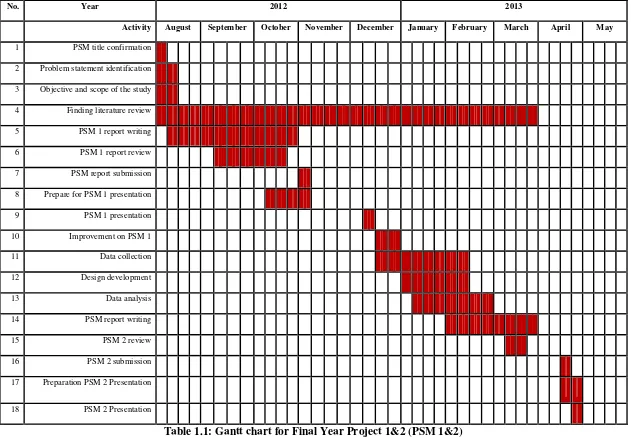
1.1 Gantt Chart For Final Year Report 1&2 6
2.1 Typical Properties of PTFE 25-27
3.1 Measuring Process of Provided Part 56
3.2 Machining process of part 2B 58-63
3.3 Machining process of part 3A 64
3.4 Machining of Part 3B 65
3.5 Machining of Part 1A 66
3.6 Threading process of Teflon and part 1B, 3B and 2A 67
4.1 Overview of the complete fabricated product 71
4.2 Analysis of weight value properties of old design pipe part 73-74
4.3 Analysis of weight value properties of prefabricated pipe part 74-75
4.4 Movement of displacement vector under certain scaling factor 79
4.5 Von Misses Stress 81
4.6 Von Misses Stress 84
4.7 The evolution of plastic strain to the propagation of the shear
band
87
4.8 The evolution of plastic strain to the propagation of shear band on
the new part
88
4.9 Teflon Properties correspond of thermal distribution analysis 90
4.10 Teflon Properties correspond of thermal distribution analysis 90
4.11 Analysis based on thermal properties on the part 92
4.12 Typical price rate based on the material apply 96
4.13 Labor Cost of Old and Prefabricated Product 97
4.14 Total Part Cost of Old Product 98
4.15 Total Part Cost of Prefabricated Product 98
ix
LIST OF FIGURES
1.1 Ejector Part 2
1.2 Specific Drawing of joining parts 3
1.3 Existing part of Ejector 4
2.12 Self Restrained Joint 17
2.13 Flange Pipe component 18
2.14 Flange Joint 18
2.15 Pipe valve 19
2.16 Nut and Bolt Pipe 20
2.17 Pipe Flange Bolt 20
2.18 Plastic Pipe Material 21
2.19 Structure of PTFE Material 25
2.20 Low Carbon Steel Pipe 30
2.21 Turning motion 36
2.22 Different turning operations 37
2.23 Drawing of threads 38
x
3.7 Hydraulic Press machine 49
3.8 Band saw machine 49
3.9 Complete design of fabrication of joining part 52
3.10 Part Preparations 53
3.11 Mild steel hollow pipe 54
3.12 Teflon Pipe 55
3.13 Flange Part 55
4.1 Apply load and restraint 77
4.2 Part deformation (Front Side) 78
4.3 Colour coded of displace vector 79
4.4 Boundary displacement area 79
4.5 Principle stress on boundary 80
4.6 Edge and Point mode 80
4.7 Stress generate process 81
4.8 Steel Material as outer part and Teflon as inner part material 82
4.9 Apply load and restraint 83
4.10 Part Deformation 83
4.11 Principle stress acting on the part 84
4.12 Strain-Hardening Material Models of Old and Prefabricated Part 86
4.13 Pipe Analysis of Heating around old pipe parts and prefabricated
parts
91
4.14 Nodal Solution 93
4.15 Thermal flux diffusion 93
4.16 Thermal flux in vectorial presentation 94
1 undoubtedly the energy transportation, such as oil and natural gas [George (2003)]. An interesting use of the pipes can be found in, example, in the Malaysia- Thailand Joint Development Area (JDA), Trans Asean Pipeline system, where gas transportation lines are interconnected by a 1540 km long pipeline system.
In industry and engineering discipline, a pipe is a round-stiff tubular section of the gas system that is made of carbon steel or plastic in function of the inner, outer or nominal diameter and the wall thickness. These measures are imposed by applicable industrial standards, such as ASME/ANSI B36.10/B36.19. The size of a pipe is based on its function and may vary from around 5 cm (2 in) to over 150 cm (60 in) in diameter [Henry (2003)].
2
In Petronas Penapisan Melaka, there are sections of operation processing, transmission and testing section. Each section was set up a piping system to operate the plant. Operations are carried out without continuously every day for gas processing and transmission because of the requirement by the customer in the power, industrial and commercial sectors throughout Peninsular and East Malaysia. However, because of the long time usage, some parts are already seasoned thereby require some fabrication of those parts.
Therefore, the aim of this study will be on the fabrication of joining parts for oil and gas piping system as shown in figure 1.1 below. The study involves with the investigation of existing products in term of design, properties, and manufacturing cost. The existing product will be redesigned with the additional of strengthening structures to improve the product. The fabrications then take place after the design is conform. The figure 1.2 below had shown the specific drawing of the parts.
3
Figure 1.2: Specific Drawing of joining parts [Petronas (2012)].
4
Figure 1.3: Existing Part of Ejector [Petronas (2012)].
This study's important to the oil and gas company where it can be a guideline for the company in implementing the suitable design and pipe fabrication processing and future work for piping fabrication. Besides that, the application of the proposed piping system can help them to increase the productivity and maintain high piping resistibility. In addition, this study's importance to become reference material for further piping development research and studying.
1.2 Aim and Objectives of the Research Work
This study essentially consisted of the following major categories which encompass,
I. Fabrication of joining parts for oil and gas piping system
II. Investigation of the existing product in terms of design, properties and
5
1.3 Scope of the Report
This report is divided into two phases which is Final Year Project (FYP 1) and 2. Overall, this report contains 6 chapters. There are introduced, literature review, methodology, result and discussion, and conclusion and recommendation.
In Chapter 1: Introduction, is briefly explained the background of the study, the design and fabrication of joining part for oil and gas piping system, followed with the problem statement, objective of the study, scope, importance of this study and the organization of the report.
In chapter 2: Literature review, the theory of piping selection and selected component with support ideas that taken from journal, books, and articles are explained in detail.
In Chapter 3: Methodology, all methods that will be discussed to achieve objectives and obtained the result explained. The systematic planning and process flow diagram (PFD) also provided to show the overall study flow.
In Chapter 4: Result and Discussion focuses on the result and data being collected from the study. Beside, the discussion of the result been gained is explained further in this chapter.
In Chapter 5: Finding and Conclusion, the final chapter of this report concludes all the finding of the study and present the suggestion and recommendation in order to improve this study in future.
1.4 Gantt Chart of the report
6
No. Year 2012 2013
Activity August September October November December January February March April May
1 PSM title confirmation
8 Prepare for PSM 1 presentation
9 PSM 1 presentation
17 Preparation PSM 2 Presentation
18 PSM 2 Presentation
7 and other equipment need for operating the system [Henry (2003)].
Piping system is a set of components including pipe, pipe fittings, flange, bolting, gasket, relief devices and the pressure retaining parts included in any stress analysis. It also includes the hangers, supports, and any other equipment necessary to prevent over stressing of the pressure retaining parts. It does not include the structure and equipment and foundations, except they may affect the stress analysis. That reason to define the design and fabrication of a system that offers a reasonable expectation of being safe when operated as intended [Philip (2005)].
8
had be listed as well as any restriction for their use. In addition the code will also stipulate various accepted standards that govern the manufacture, tolerance and installation of all components [Micheal (2003)].
![Figure 1.1: Ejector Part [Petronas (2012)].](https://thumb-ap.123doks.com/thumbv2/123dok/543526.63466/18.612.132.560.362.578/figure-ejector-part-petronas.webp)
![Figure 1.2: Specific Drawing of joining parts [Petronas (2012)].](https://thumb-ap.123doks.com/thumbv2/123dok/543526.63466/19.612.136.561.70.291/figure-specific-drawing-joining-parts-petronas.webp)
![Figure 1.3: Existing Part of Ejector [Petronas (2012)].](https://thumb-ap.123doks.com/thumbv2/123dok/543526.63466/20.612.158.561.68.292/figure-existing-ejector-petronas.webp)
![Figure 2.1: Piping system [Allen (2010)].](https://thumb-ap.123doks.com/thumbv2/123dok/543526.63466/24.612.197.491.137.348/figure-piping-system-allen.webp)
