Design and Development of Industrial Systems for Guidance and Control of Marine
Surface Vessels
1S.M.S.S.A Hamid, 2M. S. M. Aras, 3A.M.Kassem,4S.S. Abdullah
1
Department of Mechatronics, Faculty of Electrical Engineering, Universiti Teknikal Malaysia Mela ka, Hang Tuah Jaya, 76100 Durian Tunggal, Melaka Malaysia.
Tel: + 606-5552284, Fax: + 606-5552222, E-mail: [email protected]
2
Department of Mechatronics, Faculty of Electrical Engineering, Universiti Teknikal Malaysia Melaka, Hang Tuah Jaya, 76100 Durian Tunggal, Melaka Malaysia.
Tel: + 606-5552284, Fax: + 606-5552222, E-mail: [email protected]
3
Department of Mechatronics, Faculty of Electrical Engineering, Universiti Teknikal Malaysia Melaka, Hang Tuah Jaya, 75450 Ayer Keroh, Melaka Malaysia.
Tel: + 606-5552284, Fax: + 606-5552222, E-mail: [email protected]
4
Department of Electric and Electronics, Malaysia -Japan International Institute of Technology, Universiti Teknologi Malaysia, International Campus Jalan Semarak, 54100 Kuala Lumpur, Malaysia.
Tel: + 603-26154707, Fax: + 603-26910342, E-mail: [email protected]
Abstract
This paper discusses the design and development of industrial systems for guidance and control of marine surface vessels. In order to cover the large area of industrial marine guidance and control, focus has been given on the relatively high-level physical and logical design issues that dictate system capabilities, justified by a holistic view on GNC (Guidance, Navigation, and Control) systems. This project makes an effort to achieve this goal by structuring and categorizing the industrial systems and relating them to the academic framework found in the academic literature. This paper focuses on industrial methods of GNC and multi sensor monitoring system. Throughout this paper, an effort is made to relate issues, technical and safety wise to international regulations and standards in order to ensure realistic premises. The findings of this project are expected to be useful on developing remotely control self-navigated surface vessel which then could revolutionize the way of deploying and supporting underwater vehicle operation.
Keywords
Surface vessel, multi sensor system, DSV, underwater technologies.
Introduction
This project is a design and development of industrial systems for guidance and control of marine surface vessels. In an academic engineering environment it is important to stay in touch with the industry one aspires to contribute to. This project is meant to be a design concept of industrial marine guidance and control systems. A great deal of attention is given to the capabilities of current industrial systems, but limitations are also shed light upon and
solutions outlined wherever appropriate. In order to cover the large area of industrial marine guidance and control, focus has been on the relatively high-level physical and logical design issues that dictate system capabilities. This is justified by a holistic view on GNC (Guidance, Navigation, and Control) systems; in order to identify where improvement should be made one first needs to understand the system as a whole and analyse the role of each component. This project makes an effort to achieve this goal by structuring and categorizing the industrial systems and relating them to the academic framework found in the academic literature. Important issues that are touched upon are, industrial methods of guidance and control, transitions between low-speed and high-speed vessel control, following of general paths and the choice of actuator layout.
Surface Vessel Design
Development of a rapid prototyping environment for development of USV control systems at Underwater Technology Research Group Lab, Faculty of Electrical Engineering, UTeM as shown in Figure 1. This rapid prototyping environment includes modelling of the vessel and building a vessel simulator in MATLAB/ Simulink where new controllers will be developed and tuned before they are implemented in the USVs. This will ease the development of new controllers in projects with other vessels. The heading controller and way-point guidance system will be developed in this rapid prototyping environment to gain experience and improve the environment. Implementation and validation will be done in the test vessel. Table 1 shows the hull specifications.
(a)
(b)
Figure 1: The First UTeRG Surface Vessel Table 1: Hull Specifications
Hull Unit
Length 3.9624 (m)
Width 1.22 (m)
Mass 80 (kg)
Displaced volume 0.08 (m3)
The Outboard Engine - Mercury 5 Hp
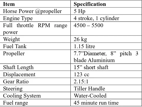
The Mercury 5hp is a great source of portable power for small skiffs, jon boats, and inflatable. It's also a popular choice as auxiliary power for sailboats as well as trolling/kicker motors for larger fishing boats. The 5hp shares many 4hp features plus a larger carburetor and propeller for increased performance [1]. The Mercury 5hp delivers outstanding fuel economy and legendary reliability. The 5M model features an integrated fuel tank for true grab-and-go portability [1]. External tank connection is standard providing the ability to add an optional external fuel tank/fuel line. The specifications for the Mercury 5 Hp are given in Table 2.
Figure 2: Engine Surface Vessel Table 2: Specifications of engine surface vessel
Item Specification
Horse Power @propeller 5 Hp
Engine Type 4 stroke, 1 cylinder Full throttle RPM range
power
4500 – 5500
Weight 26 kg
Fuel Tank 1.15 litre
Propeller 7.7”Diameter, 8” pitch 3 blade Aluminium
Oil capacity 45 ml
Features
- Compact and lightweight
- Digital CD Ignition with spark advance - High Grade Marine Alloy Construction - Stainless Steel Water Pump Housing - Rated for Saltwater Use
- Forward-Neutral Reverse Gear Shift - 1.15 Liter Fuel Tank
- Adjustable Steering Tension Control - Twist-Grip Throttle with tension Control
GPSMAP 580/585
The vessel is equipped with a Garmin GPSMAP 580/585 as shown in Figure 3 which give heading, position, velocity and rate of turn. Garmin GPSMAP 580 is a full-function chart plotter, while the GPSMAP 585 contains all the features of the GPSMAP 580 and adds fish finding capabilities [2]. The advanced keypad system on the GPSMAP 580/585 is designed to allow us to select options and enter data quickly and conveniently. The GPSMAP 580/585 has a built-in, high-sensitivity GPS module [2]. You can use the unit without external GPS antenna; however, you may receive a weak GPS signal when navigating in areas where an external antenna is required As shown in Figure 3 the GPSMAP provides RS232 interface to communicate NMEA01832 messages with the laptop. Both the Global Positioning System (GPS) signals and data from the gyrocompass is used to calculate heading. This combination provides the heading even when there is no GPS coverage. In addition we obtain a more accurate heading during and after turns. GPS
Figure 4: Surface Vessel System
The project had approached by building a surface vessel and occupies it with a set of navigation sensors as shown in Figure 4. The navigation system consists of GPS system and seabed monitoring system. Information from both sensory systems then monitored through a monitoring GUI made to ease the monitoring process by users. The system had been made to store and transmits data collected by the system. This will then enable a navigation system to access the current condition of the surface vessel in both location and underwater orientation position.
Experimental Testing
The system manages to collect the essential data on the current location of the vessel as well as the seabed condition under the vessel. The system enables the operator of the vessel to control the vessel either from the top of the vessel or remotely from shore safely as it constantly provide the position of the vessel on the surface as well as the unlevelled. seabed condition below the vessel which could jeopardize the safety of the vessel and the USV serviced by the vessel.
Figure 5 shows the Manual Cruise PID controller Simulink Block diagram. So, the try to using this concept for auto-heading controls. The model obtained from experimental and reviewed paper [3] . Figure 5 is the simulink for heading control. The model USV obtain from [4] while the Engine Model obtained from System Identification of our experimental.
Figure 6: System response
In Figure 6 shows the system response, at initial the response have negative response, this because motor have an in- rush current. At initial condition the motor is not static and sudden high current applied then the resultant as shown in Figure 6. Only PI controller will be used in this system. The values of Proportional and Intgeral gain are small, 0.14 and 0.13 respectively as shown in Figure 7.
Figure 7: PID controller
In simulations results obtained for USV model as given in Table 3. The Quick PID and Non-overshoot PID obtained from review paper [5]. The same value of PID parameter applied in simulink as shown in Figure 7. The results for the both PID parameter is not stable. This is because the model of USV stated in simulink actually already accounted with overall model. The simulation as shown in Figure 8 is already done previously.
Table 3: Simulation results for PID parameter Gain Quick
PID (a)
Non-overshoot PID
(b)
Our Simulation (c)
Kp 16 3 0.44
Ki 1 2 0.13
Kd 0.5 0.5 0
Figure 8: New PID controller with USV model
(a)
(c)
Figure 9: (a) Quick-PID, (b) Non-overshoot PID, (c) Our PID
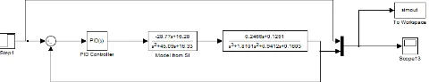
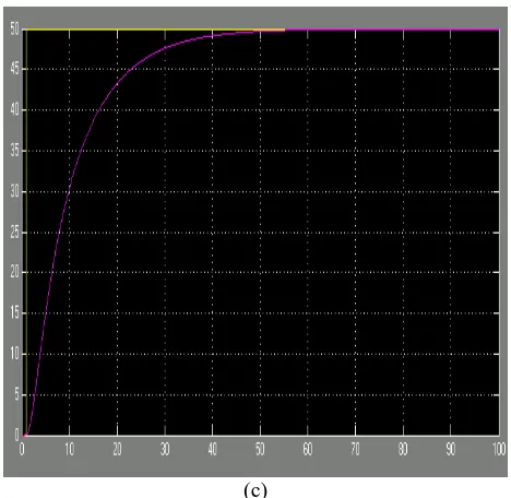
Figure 10 shows the simulink of simulation results based on review paper [6]. The general adopted scheme of the controlled system shown in Figure 10, where the vehicle is represented by the transfer function block. The step response of this system is shown in Figure 11.
Figure 10: Closed loop feedback system
Figure 11: Step response for closed loop feedback system
Figure 12: PID control scheme
Figure 13: Step response for PID control system
Figure 14: System response overshoot
Figure 14. In heading controls we suppose don’t want overshoot. Reasons are particularly important when the vehicle operates in a dangerous environment, like that found in offshore structures or during archeological activities. The necessity of assuring vehicle integrity while operating near the coral or proximity of submersed installations and the need to prevent damage, without comprising the system efficiency. So we have to tune a PID controller parameter as shown in Figure 6. Figure 7 shows the best system response obtained.
Figure 15: Best PID control after tuning
Another simulation, we change the set point based on previous model with reference model as shown in Figure 15. The PID parameters still remain. Figure 16 shows the system response. It can follow the set point that we set.
Figure 16: Set point and model reference new setting
Figure 17: System response due to heading.
Digital Compass
Digital Compass Sensor will integrate with Inertial Measurement Unit (IMU) and interface using microbox as shown in Figure 18. The Digital Compass fully integrated
compass module that combines 2-axis magneto-resistive sensors with the required analogue and digital support circuits, and algorithms for heading computation.
Figure 18: Digital Compass
NI DAQ Card
Data acquisition (DAQ) is the process of measuring an electrical or physical phenomenon such as voltage, current, temperature, pressure, or sound with a computer. A DAQ system consists of sensors, DAQ measurement hardware, and a computer with programmable software. Compared to traditional measurement systems, PC-based DAQ systems exploit the processing power, productivity, display, and connectivity capabilities of industry-standard computers providing a more powerful, flexible, and cost-effective measurement solution.
The NI USB-6009 provides connection to eight analog input (AI) channels, two analog output (AO) channels, 12 digital input/output (DIO) channels, and a 32-bit counter with a Full-Speed USB interface.
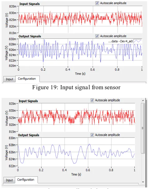
Figure 19: Input signal from sensor
Figure 21: Input signal dan testing from sensor
Figure 22: Filtered signal with sensor testing.
Conclusion
This project still a lot of research can be done. Simulation using Matlab/Simulink for control design and modeling successfully for auto-heading control system. The system can be approved to more intelligent Unmanned Surface Vessel.
Acknowledgement
Special appreciation and gratitude to honorable University (UniversitiTeknikal Malaysia Melaka, UTeM and UniversitiTeknologi Malaysia, UTM) especially to the both Faculty of Electrical Engineering for providing the financial as well as moral support to complete this project successfully
References
[1] http://www.mercurymarine.com/service- and-support
[2] http://files.sotmarket.ru/instr/gps_navigatori/garmin/garmin_gpsmap _585.pdf
[3] Zhijie Tang, Luojun, and Qingbo He, A Fuzzy-PID Depth Control Method with Overshoot Suppression for Underwater Vehicle, School of Mechatronics Engineering and Automation, Shanghai University, Shanghai, 2010.
[4] Modeling, Identification, and Analysis of Limit-Cycling Pitch and Heave Dynamics in an ROV, Sergio M. Savaresi, Fabio Previdi, Alessandro Dester, Sergio Bittanti, Dipartimento di Elettronicae Informazione, Politecnico di Milano, Italy, Dipartimento di Ingegneria, Università degli Studi di Bergamo, Dalmine,Gaymarine Ltd., Turate, 2004
[5] Combine Sliding Mode Control and Fuzzy Logic Control for Autonomous Underwater Vehicles, Feijun Song and Samuel M . Smith University of Limerick, Ireland, Advanced Fuzzy Logic Technologies
in Industrial Applications, 2009.
[6] Mohd Shahrieel Mohd Aras, Eric Chee Sai Hoo, Syed Najib Bin Syed Salim, Intan Azmira binti Wan Abd Razak, Mohd Hendra bin Hairi, Comparison of Fuzzy Control Rules using MATLAB Toolbox and Simulink for DC Induction Motor-Speed Control, International Conference of Soft Computing and Pattern Recognition, 2009.
[7] Study of the Effect in the Output Membership Function When Tuning a Fuzzy Logic Controller, Mohd Shahrieel Mohd Aras, Fadilah binti Abdul Azis,Syed Mohamad Shazali b Syed Abdul Hamid, Fara Ashikin binti Ali, Dr Shahrum Shah b Abdullah, 2011 IEEE International Conference on Control System,Computing and Engineering (ICCSCE 2011).