“I admit to have read this report and it has followed the scope and quality in Partial Fulfillment of Requirement for the Degree of Bachelor of Mechanical Engineering
(Structure and Material)”
MODELING AND STUDY OF VERTEBRA UNDER COMPRESSIVE LOADING
RUSDI BIN YUNUS
This report submitted in partial fulfillment of the requirements for Degree of Bachelor in Mechanical Engineering (Structure and Material)
Faculty of Mechanical Engineering Universiti Teknikal Malaysia Melaka
III
“I agree that this report is my own work except for some summaries and citation which I have already stated”
Signature : ………
IV
ACKNOWLEDGEMENT
I would like to express my sincere gratitude to my supervisor Dr. Mohd Juzaila bin Abd Latif for his germinal idea, invaluable guidance and constant support in making this research possible. I am truly grateful for his progressive vision about my project, his tolerance of my mistake and his commitment to my project. I also sincerely thanks for the time spent proofreading and correcting my mistake.
V
ABSTRACT
VI
ABSTRAK
VII
CONTENTS
ACKNOWLEDGEMENT ... iv
ABSTRACT ... v
ABSTRAK ... vi
CONTENTS ... vii
FIGURES ... ix
TABLES ... xi
CHAPTER I ... 1
LITERATURE REVIEW... 1
1.1 Introduction ... 1
1.2 Structural Anatomy of Lumbar Spine ... 3
1.3 Biomechanics of Spine ... 9
1.4 Low Back Pain ... 13
1.5 Computational Method ... 14
1.6 Previous Studies ... 19
1.7 Overall Summary ... 23
VIII
CHAPTER II ... 25
METHODOLOGY ... 25
2.1 Literature Review ... 25
2.2 Develop 3D Model of Vertebra ... 25
2.3 Finite Element Model of Vertebra Under Compressive Loading ... 27
CHAPTER III ... 35
RESULTS ... 35
3.1 Introduction ... 35
3.2 Validation... 35
3.3 Stress Distribution of Vertebra with Disc ... 36
3.4 Stress Distribution of Vertebra Without Disc ... 37
CHAPTER IV ... 38
DISCUSSION ... 38
4.1 Introduction ... 38
4.2 Vertebra With Disc ... 38
4.3 Vertebra without Disc ... 40
CHAPTER V ... 41
CONCLUSION AND RECOMMENDATION ... 41
5.1 Conclusion ... 41
5.2 Recommendation ... 41
IX
FIGURES
Figure 1. 1: Human spine. ... 2
Figure 1. 2: The Lumbar Spine ... 3
Figure 1. 3: Classification of spine ... 4
Figure 1. 4: Vertebral Body... 4
Figure 1. 5: Facet Joint ... 5
Figure 1. 6: Articular Cartilage ... 5
Figure 1. 7: Intervertebral disc that lies between vertebra ... 6
Figure 1. 8: Vertebral disc highlighting the annulus rings surrounding nucleus. 7 Figure 1. 9: Vertebral disc highlighting the annulus fibers at 30deg to the end-plate. ... 7
Figure 1. 10: Various ligament of the spine. ... 8
Figure 1. 11: Low back muscle... 9
Figure 1. 12: Cortical bone and cancellous bone ... 10
Figure 1. 13: Vertebral compressive strength ... 11
Figure 1. 14: Compressive loading of intervertebral disc. ... 12
Figure 1. 15: : Load sharing in lumbar spine in normal and degeneration disc. 13 Figure 1. 16: Disc degeneration following internal disc disruption and herniation ... 14
Figure 1. 17: Material properties of cortical bone ... 15
Figure 1. 18: Material properties of cancellous bone... 16
Figure 1. 19: Material properties of disc nucleus ... 17
Figure 1. 20: Material properties disc annulus ... 18
X
Figure 1. 23: L5 vertebra as solid cortical bone ... 20
Figure 1. 24: L5 vertebra as a hollow cortical shell ... 21
Figure 1. 25: The maximum displacement of the FE model in different loading ... 22
Figure 1. 26: The Von Misses distribution of L1-L2 segment ... 22
Figure 2. 1: L4 lumbar spine 3D model in SolidWork software ... 26
Figure 2. 2: Intervertebral disc ... 26
Figure 2. 3: Vertebral body ... 27
Figure 2. 4: Plane... 28
Figure 2. 5: Intervertebral Disc ... 29
Figure 2. 6: Vertebral Body... 29
Figure 2. 7: Left:assembly of disc-vertebra,right:assembly of plane-vertebra ... 29
Figure 2. 8: Tetrahedral mesh... 31
Figure 2. 9: Yellow: plane-disc interaction; Orange: disc-vertebrae is tied ... 32
Figure 2. 10: Yellow: plane-vertebrae interaction ... 32
Figure 2. 11: Boundary condition ... 33
Figure 2. 12: Load is applied at reference point ... 34
Figure 3. 1: FEM result of simplified model ... 36
Figure 3. 2: FEM result of disc-vertebra model ... 36
Figure 3. 3: FEM result of vertebra without disc model ... 37
Figure 4. 1: Classification of vertebral compression fracture... 39
XI
TABLES
Table 2. 1: Specification of FEM Model... 28
Table 2. 2: Dimension of FEM Model ... 28
Table 2. 3: material properties used in the model ... 30
Table 2. 4: component and its number of mesh element ... 30
1
CHAPTER I
LITERATURE REVIEW
1.1 Introduction
Human spine is a complex structure that provides both mobility and stability, and also protects the spinal cord. The normal human spine consists of twenty four vertebras where intervertebral disc lies in the vertebral. From Figure 1.1, the spine forms three curves, named according to region and position:
1. Cervical: 7 vertebrae (C1-C7) 2. Thoracic: 12 vertebrae (T1-T12) 3. Lumbar: 5 vertebrae (L1-L5)
2
Figure 1. 1: Human spine. Adapted from Netter (2006)
3
Figure 1. 2: The Lumbar Spine
Some researchers have clarified that intervertebral disc degeneration that resulting pain is determined by genetic inheritance (MacGregor et al., 2004) and all the aspect of back pain behavior is dominated by psychosocial characteristic (Waddell, 1998). However, mechanical load remains one of the most important aspects that can aggravate low back pain and disc degeneration.
1.2 Structural Anatomy of Lumbar Spine
4
Figure 1. 3: Classification of spine
1.2.1 Vertebral Body
The vertebral body makes the front bony structure of the vertebra. From Figure 1.4, the vertebral body consists of cortical bone at the outer shell and cancellous bone at the inside. The cancellous bone is less compact compared to the cortical bone. The pedicle at the upper end of the posterior supporting the posterior elements.
5
1.2.2 Facet Joints
Figure 1.5 and Figure 1.6 show the facet joints and articular cartilage in human spine. Facet joints are located at the back of the spine (posterior). The joint allows motion of the bone. The bone moves smoothly without friction because the end of most joints is covered by soft material that called articular cartilage.
Figure 1. 5: Facet Joint
6
1.2.3 Intervertebral Disc
From Figure 1.7, intervertebral disc lies between the vertebral. The intervertebral disc makes up 20-33% of the vertebra height and consists of three parts, nucleus pulposus, the annulus fibrosis and the cartilaginous end-plate. The functions of intervertebral disc are:
• Movement of fluid within the nucleus allows the vertebra to rock back and forth
• Provide flexibility to the vertebra
• The movement space of the 24 vertebra is maintain by intervertebral disc
• Absorb external loading that act like absorbers
• Allow flexion and extension
Nucleus is at the centre and surrounded by annulus, a series of strong ligament. 25% of the areas of the disc are formed by nucleus. No clear boundary can be found between nucleus and annulus even though both parts are significantly difference in structure. Most of shocks of the spine are absorbed by the nucleus part. The pressure that acts to the disc will be distributed evenly across the disc. Together with lumbar vertebral body, 80% of compressive loading in standing position are resists by these parts (N, JB et al., 1988)
7
The nucleus is located at the centre area of the disc. The nucleus is very stiff that consist of a collagen and proteoglycans. The water content of pulposus ranges from 70-90% which tends to reduce with age (Kalyanrao, 2002). Compare to cervical and thoracic region, the size of the disc larger in the lumbar region. The disc also is more posterior in lumbar region compare to thoracic region.
The annulus is composed of concentric ring of fibrous cartilage that surrounds and protects the soft material located in the centre of the disc. The fibers run on diagonal angle which is inclined at 30deg to the disc plane.
Figure 1. 8: Vertebral disc highlighting the annulus rings surrounding nucleus. Adapted from Kalyanrao (2002)
8
1.2.4 Ligaments
Ligaments are strong connective tissue that attach to bone. Ligaments protect the spine from injury and help stabilize joints. It gives natural support to avoid injury to the spine from extreme movements. From Figure 1.10, there are seven types of ligaments in the lumbar spine which are connected to the front and back section of the vertebrae.
Figure 1. 10: Various ligament of the spine. Adapted from Kalyanrao (2002)
1.2.5 Muscles
9
Figure 1. 11: Low back muscle
1.3 Biomechanics of Spine
Biomechanical in spine is related to the spine mechanical behavior as subjected to loads. There are three fundamental biomechanics of spinal column:
• Ensure that the load transfer steadily along the column.
• Prevent harmful to the spinal cord from damaging force.
• Give enough flexibility to the spinal column.
10
1.3.1 Compressive Strength of Vertebra
The compressive strength of the vertebra is very important issue. From Figure 1.13, several studies had been carried out to carry out a proper compressive strength of the vertebral body. It was found that the reason that the strength of vertebra different in each level is due to the size of vertebral body alone.
The load on the vertebra is transferred by the two structures of vertebral body which are the cortical bone and the cancellous bone which is shown in Figure 1.12. Cancellous bone is spongy bone and occupied a large area of vertebral body compare to cortical bone. Due to this bone structure, cancellous bone has good absorbing abilities.
11
12
There is a conflict between previous studies on the loads that shared between these two structures. An experiment was to resolve the conflict on which structure that support major load. The intact vertebral strength was compared with the experiment in which the loads were applied without the shell. It was found that under compressive load, the cancellous bone contributes 25-55% of the strength of lumbar vertebral body (Kalyanrao, 2002).
1.3.2 Biomechanics of Intervertebral Disc
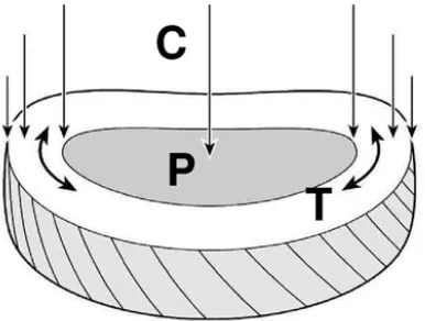
The intervertebral disc is viscous in nature. The disc is a major load carrying in human spine especially in compressive load. Compressive load that act axial to the disc creates a hydrostatic pressure in the nucleus and tensile stresses in the annulus. Intervertebral disc withstand most of the compressive loading that act on the plane.
Figure 1. 14: Compressive loading of intervertebral disc. Adapted from
Pollintine et al. (2004)1
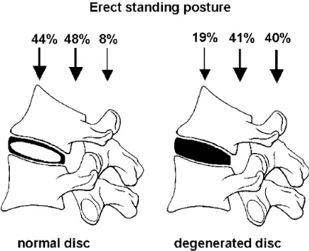
Intervertebral disc degeneration affects the loads that distribute across the disc. In normal disc, most of the load spread evenly anterior and posterior of the vertebral body. Only 8% of the applied forces resisted by the neural arch. However, about 40% of compressive load resisted by neural arch in degeneration disc while the anterior region resists only 19%.
13
Figure 1. 15: : Load sharing in lumbar spine in normal and degeneration disc.
Adapted from Pollintine et al. (2004)2
Many tests have been carried out to study disc on the disc at constant compressive loads. It was found that there is no disc herniation even when long incision was made on the annulus fibrosis. Another test was carried out by Brown and found that vertebral body is the first element to fracture when subjected to compressive load. There is no failure of disc due to herniation (Kalyanrao, 2002).
1.4 Low Back Pain
As an important human load-bearing structure, the lower back which is called lumbar spine region is the most flexible and receives the most stress compare to other region. Due to this bone structure which supports the weight from upper body, most pain is felt at this area which is known as low back pain. Anatomy structure of lumbar spine plays role that contribute to lower back pain.
L4-L5 intervertebral disc encounter 80-90% of lumbar flexion/extension in lumbar spine biomechanical motion. The occurrence of low back pain are high when the lumbar region experience forward bending, rotation or when trying to pick up