Volume 2012, Article ID 268964,10pages doi:10.1155/2012/268964
Research Article
Effects of Structural Parameters on the Dynamics of a Beam
Structure with a Beam-Type Vibration Absorber
Mothanna Y. Abd,
1Azma Putra,
2Nawal A. A. Jalil,
1and Jamaludin Noorzaei
31Department of Mechanical and Manufacturing Engineering, Faculty of Engineering, Universiti Putra Malaysia, 43400 Serdang,
Selangor, Malaysia
2Department of Structure and Materials, Faculty of Mechanical Engineering, Universiti Teknikal Malaysia Melaka, Hang Tuah Jaya,
76100 Durian Tunggal, Melaka, Malaysia
3Department of Civil Engineering, Faculty of Engineering, Universiti Putra Malaysia, 43400 Serdang, Selangor, Malaysia
Correspondence should be addressed to Nawal A. A. Jalil,[email protected]
Received 30 April 2012; Revised 21 September 2012; Accepted 23 September 2012
Academic Editor: Abul Azad
Copyright © 2012 Mothanna Y. Abd et al. This is an open access article distributed under the Creative Commons Attribution License, which permits unrestricted use, distribution, and reproduction in any medium, provided the original work is properly cited.
A beam-type absorber has been known as one of the dynamic vibration absorbers used to suppress excessive vibration of an engineering structure. This paper studies an absorbing beam which is attached through a visco-elastic layer on a primary beam structure. Solutions of the dynamic response are presented at the midspan of the primary and absorbing beams in simply supported edges subjected to a stationary harmonic load. The effect of structural parameters, namely, rigidity ratio, mass ratio, and damping of the layer and the structure as well as the layer stiffness on the response is investigated to reduce the vibration amplitude at the fundamental frequency of the original single primary beam. It is found that this can considerably reduce the amplitude at the corresponding troublesome frequency, but compromised situation should be noted by controlling the structural parameters. The model is also validated with measured data with reasonable agreement.
1. Introduction
A beam-type absorber is one of the techniques to reduce undesirable vibration of many vibrating systems, such as a synchronous machine, mounting structure for a sensitive instrument, and other continuous structure in engineering. The absorber system usually consists of a beam attached to the host structure using an elastic element. The natural frequency of the absorber is then tuned to be the same as the troublesome operating frequency of the host structure to create counter force, which in return reduces the vibration of the structure. As beams are important structures in civil or mechanical engineering, several works have also been established to investigate the performance of the absorbing beam which is attached also to a beam structure.
Among the earliest studies of the double-beam system is one proposed by Yamaguchi [1], which investigated the effectiveness of the dynamic vibration absorber consisting
of double-cantilever visco-elastic beam connected by spring and viscous damper. The auxiliary beam is attached to the center of the main beam excited at its end by a sinusoidal force. It is found that the amplitude at resonances of the main beam is sensitive to the stiffness and mass of the absorbing beam. The damping ratio was formulated as a function of mass and layer stiffness of the absorber. Vu et al. [2] studied the distributed vibration absorber under stationary distributed force. A closed form was developed by utilizing change of variables and modal analysis to decouple and solve differential equations. Oniszczuk [3] studied the free vibrations of two identical parallel simply supported beams continuously joined by an elastic layer. The eigen frequencies and mode shapes of vibration of the double-beam system were found using the classical assumed mode summation.
w1
w2
Primary beam
Absorbing beam Linear spring-damper ... L/2
k c
L x
F0eiωt
(a)
F0eiωt
Main beam element
Visco-elastic layer element
Absorber beam element
w1
w2
m1
k c
K2=eK1
K1=E1I1
µm1
(b)
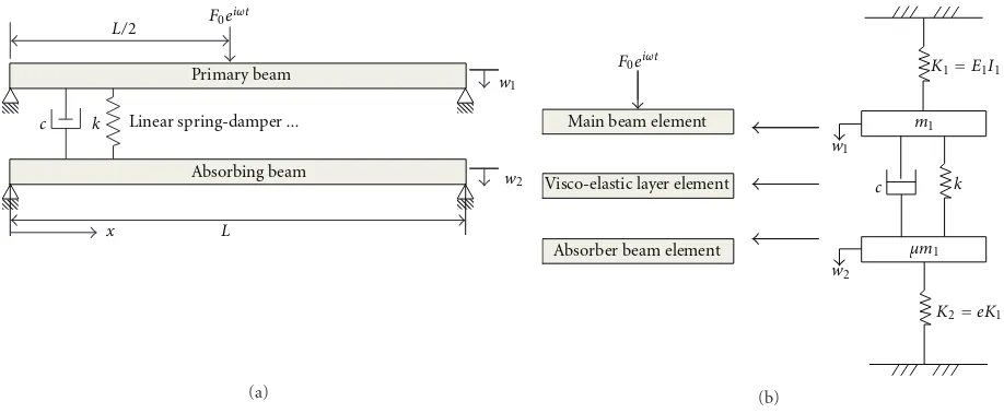
Figure1: (a) Schematic diagram of a visco-elastically connected simply supported double-beam system and (b) the two-degree-of-freedom system of distributed lumped parameter model.
condition is connected to the main beam by spring and damper components. In the study, an optimum tuning method to reduce the main beam vibration was proposed. Another structural analysis and optimum design of a dynamic absorbing beam with free edges was studied by Chen and Lin [5]. The effect of mass ratio and the stiffness layer on the vibration response was discussed.
The effect of different forcing types on the double-beam system has also been discussed by several authors. Zhang et al. [6] studied vibration characteristics of the double-beam system under axial compressive load. The studies were limited for two identical simply supported double-beam system and the effect of the axial load on the beams vibration amplitude was reported. Abu-Hilal [7] studied the effect of a moving constant load on the dynamic response of the beams. This was done for different values of speed parameter, damping ratio, and stiffness parameter.
Several works focus on the development of mathematical model to provide solutions of the vibration response. De Rosa and Lippiello [8] studied free vibration of double-identical beam system using the Differential Quadrature Method (DQM). Sadek et al. [9] presented a computational method for solving optimal control of transverse vibration of a two-parallel-beam system based on legendry wavelets approach. It is found here that the reduction of the beam vibration depends on the spring location on the beam.
This paper investigates the effect of structural param-eters, namely, the rigidity ratio, mass ratio, damping loss factor, the stiffness, as well as the damping ratio of the layer on the dynamic response of simply supported double-beam system to provide a thorough analysis. The discussion is limited on controlling the fundamental mode of a single-beam structure using a dynamic absorbing single-beam. The fol-lowing section discusses the derivation of the mathematical model.
2. Mathematical Modeling
The schematic diagram of a beam connected with an absorbing beam having the same length L and simply supported is shown inFigure 1(a). Here distributed lumped system of two degrees of freedom is assumed, where the visco-elastic element between the beams consists of parallel distributed springs and dampers as shown inFigure 1(b).
The equation of motion of the dynamic model can therefore be written as
E1I1∂ 4w
1
∂x4 + m1w¨1+c( ˙w1−w˙2) + k(w1−w2)=Pe
iωt,
(1)
E2I2∂ 4w
2
∂x4 + m2w¨2+c( ˙w2−w˙1) +k(w2−w1)=0, (2) where P = F0δ(x−L/2) is the external point force with frequency ω at the midspan of the beam, F0 is the force magnitude, K=EIis the flexural rigidity, cis the damping constant,kis the stiffness constant of the viscous layer, and mis the mass of the beam. The subscripts 1 and 2 refer to the main beam and the absorber beam, respectively. The damping of the beam can be introduced by replacing the flexural rigidity in (1) and (2) by K(1 +iη), whereηis the damping loss factor. The vertical displacement of the main beamw1 and the absorberw2can be expressed as a series expansion in terms of mode shape functionXn(x) for thenth mode.The amplitudes in generalized time coordinatesq1nare given by
w1(x,t)= ∞
n=1
Xn(x)q1n(t), (3)
w2(x,t)= ∞
n=1
10−2
10−3
10−4
10−5
10−6
10−7
A
mplitude (m/N)
10 20 30 40 50 60
Frequency (Hz)
e=0.25
e=0.5
e=0.75
e=1 Single beam
(a)
10−2
10−3
10−4
10−5
10−6
10−7
A
mplitude (m/N)
10 20 30 40 50 60
Frequency (Hz)
e=0.25
e=0.5
e=0.75
e=1 Single beam
(b) 10−2
10−3
10−4
10−5
10−6
10−7
A
mplitude (m/N)
10 20 30 40 50 60
Frequency (Hz)
e=0.25
e=0.5
e=0.75
e=1 Single beam
(c)
10−2
10−3
10−4
10−5
10−6
10−7
A
mplitude (m/N)
10 20 30 40 50 60
Frequency (Hz)
e=0.25
e=0.5
e=0.75
e=1 Single beam
(d)
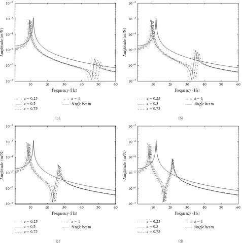
Figure2: Effect of the rigidity ratioeand the mass ratioµon the vibration amplitude at the midspan location of the primary beam: (a)
µ=0.1, (b)µ=0.2, (c)µ=0.4, and (d)µ=0.8.
where xis the position on the beam at which the load is applied. For the simply supported boundary condition, the nth mode shape function can be written as
Xn(x)=sin(σnx), (5)
where σn is the eigenvalue of the mode shape which can be expressed as:
σn= nπ
L . (6)
The orthogonality conditions can be used for simplifying the equations of motion which is represented in the following form [1]:
L
0 Xn(x)Xm(x)dx=0 , n=/m.
(7)
Equations (3) and (4) can be substituted to (1) and (2). Multiplying both sides of the equations by mode shape function Xm then integrating through the beam length
10−2
a matrix form for the equations of motion expressed as (see Appendix) rigidity ratio. The damping of the layer between the main beam and the absorbing beam can be approached by using the concept of “mixed damping ratio” in discrete dynamic
vibration absorber [10]. The damping ratio of the visco-elastic layer can be defined as
ξ= c
2m2ωn =
c
2µm1ωn, (9)
where ωnis the original natural frequency of the primary beam (without the absorber attached) which is given by
ωn=
E1I1σn4 m1 .
(10)
10−2
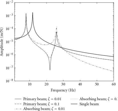
Figure 4: Effect of visco-elastic layer damping on the vibration amplitude at the midspan location of the double-beam system (e
=0.25,µ=0.4,η1=η2=0.01).
to clearly identify the distinct responses in the resonant frequencies. By defining the amplitude q in terms of the complex exponential notation it gives
whereQis the complex amplitude ofq. Substituting (11) into (8) yields
where the solutions for the complex amplitude of the frequency response function in terms of the receptance, that is,Q/F0 can then be obtained for each mode nwhich are given by
As observed from (13) and (14), the double-beam structure is expected to have two natural frequencies for each mode of vibration, as the system is modeled using two-degree-of-freedom system. It can also be seen in (13), where for the lumped parameter system with K1 = 0 and for an undamped case wherec=0, the magnitude of the numerator is proportional tok−ω2m2. The main beam amplitude can therefore be suppressed to zero by tuning the layer stiffness and the mass of the absorbing beam to be equal to the forcing frequency, that is, ω = k/m2. The subsequent sections discuss the effect of structural parameters on the response in (13) and (14).
3. Effects of Rigidity and Mass Ratio
In this investigation, the rigidity ratio and mass ratio are varied to observe their effects on the main beam response. This is calculated for a steel beam (Young’s modulusE = 2.1×10¹¹Pa, densityρ = 7800 kg/m3) having length 2 m, width 0.065 m, and thickness 0.02 m. The stiffness of the layer is assumed 100 kN/m. The calculation here is done for the first mode of vibration (n =1) for each beam.Figure 2 shows the vibration amplitude for the first two resonances of the primary beam plotted in logarithmic scale. Here the damping ratio of the visco-elastic layer and the structural
damping loss factor of the beams are assumed very small, that is,ζ=η=0.01.
10−2
10−3
10−4
10−5
10−6
10−7
10−8
A
mplitude (m/N)
10 20 30 40 50 60
Frequency (Hz)
Primary beam;η1=0.01 Absorbing beam;η2=0.1 Single beam;η1=0.01
(a)
10−2
10−3
10−4
10−5
10−6
10−7
10−8
A
mplitude (m/N)
10 20 30 40 50 60
Frequency (Hz)
Primary beam;η1=0.1 Absorbing beam;η2=0.01 Single beam;η1=0.1
(b) 10−2
10−3
10−4
10−5
10−6
10−7
10−8
A
mplitude (m/N)
10 20 30 40 50 60
Frequency (Hz)
Primary beam;η1=0.1 Absorbing beam;η2=0.1 Single beam;η1=0.1
(c)
10−2
10−3
10−4
10−5
10−6
10−7
10−8
A
mplitude (m/N)
10 20 30 40 50 60
Frequency (Hz)
Primary beam;η1=0.1 Absorbing beam;η2=0.1 Single beam;η1=0.1
(d)
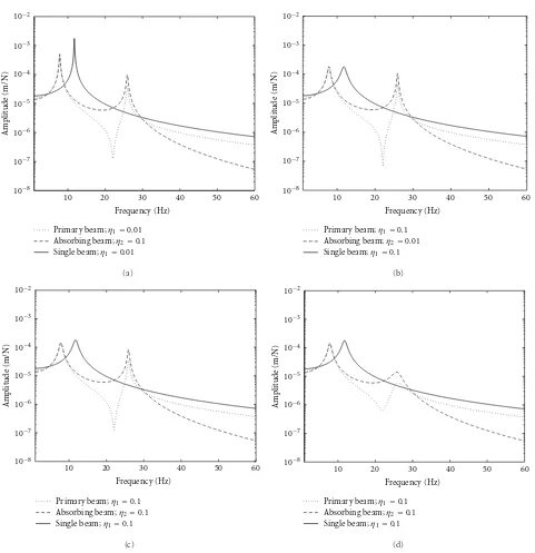
Figure5: Effect of structural damping of the beam on the vibration amplitude at the midspan location of the double-beam system (e=0.25,
µ=0.4): (a)–(c)ζ=0.01 and (d)ζ=0.1.
also be observed that the amplitude at the second resonance increases as the mass ratio is increased.
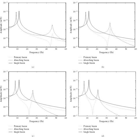
Figure 3presents the amplitudes of the primary beam
and the absorbing beam. Both amplitudes at the first reso-nance can be seen not affected by the mass ratio. However, the response of the primary beam at the second resonance is considerably lower than that of the absorbing beam for low mass ratio, but both amplitudes become comparable as the mass ratio increases. As also seen in Figure 2, the compromised situation is that the vibration amplitude of the primary beam becomes lower as the mass ratio increases. The
amplitude of the absorber at the second resonance can also be observed to have negligible effect due to the change of mass ratio, and it steeply decreases above this resonant frequency.
4. Effect of Damping and Layer Stiffness
10−2
10−3
10−4
10−5
10−6
10−7
10−8
A
mplitude (m/N)
10 20 30 40 50 60
Frequency (Hz)
Primary beam;β=50 Primary beam;β=350 Absorbing beam;β=50
Absorbing beam;β=350 Single beam
(a)
10−2
10−3
10−4
10−5
10−6
10−7
10−8
A
mplitude (m/N)
10 20 30 40 50 60
Frequency (Hz)
Primary beam;β=50 Primary beam;β=350 Absorbing beam;β=50
Absorbing beam;β=350 Single beam
(b)
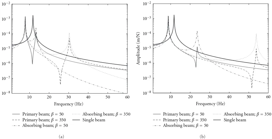
Figure6: Effect of visco-elastic stiffness on the vibration amplitude at the midspan location of the double-beam system (e=0.25): (a)µ= 0.1 and (b)µ=0.4.
Signal analyzer DAQ (data acquisition)
Power amplifier
Shaker
Main beam Accelerometer
transducerForce
Rubber pieces
Supporting columns Absorber beam
00:00
(a)
Shaker
Accelerometer
Primary beam
Rubber
Absorbing beam
(b) Figure7: (a) Diagram of the experimental setup and (b) laboratory test.
beam and the absorbing beam as the damping is increased. At this frequency, the primary beam and the absorber move out of phase for which the role of the visco-elastic layer damping is important to absorb the vibration energy. At the first resonance, as the two beams move in-phase, the layer damping can therefore be seen to have negligible effect on the vibration amplitude.
×10−3
2
1.8
1.6
1.4
1.2
1
0.8
0.6
0.4
0.2
0
A
mplitude (m/N)
5 10 15 20
Frequency (Hz)
Experiment Theory
(a)
×10−3
2
1.8
1.6
1.4
1.2
1
0.8
0.6
0.4
0.2
0
A
mplitude (m/N)
5 10 15 20
Frequency (Hz)
Experiment Theory
(b)
×10−3
2
1.8
1.6
1.4
1.2
1
0.8
0.6
0.4
0.2
0
A
mplitude (m/N)
5 10 15 20
Frequency (Hz)
Experiment Theory
(c)
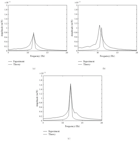
Figure8: Comparison of experimental and theoretical results of the vibration amplitude of the double-beam system for the case of (a) ST-ST, (b) ST-WD, and (c) ST-AL.
also increased (seeFigure 5(c)). Figure 5(d)shows that the amplitude of the second resonance is mainly controlled by the damping of the visco-elastic layer.
Figure 6 plots the results for the effect of stiffness of the visco-elastic layer. Here the stiffness is presented using a non-dimensional parameter as a function of the rigidity and length of the main beam, that is,β = kL4/K1. By reducing the stiffness of the layer, the second resonance shifts to low frequency, while no effect is given to the first resonance. Again same for the case of the layer damping, the in-phase motion of both beams at the first resonance will not be affected by the hardness (stiffness) of the layer. As the mass
ratio increases, this frequency shift becomes greater, which also reduces the frequency gap of the two resonances.
5. Experimental Validation
Figure 7 shows the schematic diagram and the laboratory
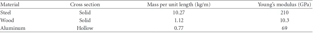
Table1: Physical parameters of the materials used in the experiment.
Material Cross section Mass per unit length (kg/m) Young’s modulus (GPa)
Steel Solid 10.27 210
Wood Solid 1.12 10.3
Aluminum Hollow 0.77 69
the midspan of the primary beam, the edge condition has negligible effect on the vibration amplitude.
The primary beam was excited by broadband pseudo-random signal at location close to the midspan of the primary beam using TIRA electromagnetic shaker type TV50018. The input force was measured by a Dytran force gauge type 1051V1. A stud was tightly bolted on the transducer surface and then glued to the beam surface using an epoxy glue. A 200 mm long stinger was used to connect the force gauge and the shaker to minimize the effect of moments transmitted from the shaker. A Dytran accelerometer type 3225F1 was attached exactly at the mid point to measure the vibration amplitude.
The experimental test was conducted with the primary beam made of steel having thickness 20 mm, width 60 mm, and length 2 m. Four measurement cases were made with different configuration and material of the absorber beam as follows:
(a) steel single beam without absorber (ST),
(b) steel main beam with steel absorber beam; double-identical beams (ST-ST),
(c) steel main beam with wood absorber beam (ST-WD), and
(d) steel main beam with aluminum absorber beam (ST-AL).
A rubber material was used as the viscoelastic layer between the beams having stiffness of 131 kN/m.
The physical parameters of the beam materials are listed inTable 1.
Figure 8presents the experimental results for the double-beam structure. It can be seen that it demonstrates good agreement with the theory especially around the resonance, although for each case, broader frequency response from the measured results can also be observed, which slightly overestimated the model.
6. Conclusions
The effect of structural parameters on the dynamic response of a beam structure attached with a beam vibration absorber through a visco-elastic layer under a stationary harmonic load has been studied. The amplitude of the original primary single beam at the fundamental frequency can be consider-ably reduced. It is found that increasing the rigidity ratio shifts the resulting resonances of the double-system to higher frequency but gives small effect on reducing the vibration amplitude of the resonances. Reducing the mass ratio reduces considerable level of the second resonance of the primary beam as well as widens the gap between the resonant
frequencies. However, this increases the first resonance to approach the troublesome resonant frequency of the original single beam but further reduces the vibration of the primary beam, a compromised situation which should be taken into account in the absorber design. The same phenomena apply for the absorbing beam, but it does not affect its vibration amplitude. Adding more damping to the layer has been shown to reduce only the second resonant amplitude. The amplitude at the first resonance can be reduced by increasing the damping of the primary beam. Meanwhile, increasing the layer elasticity (reducing stiffness) reduces the second resonance. The theoretical results have been validated by experimental data with a reasonable agreement.
Appendix
Substituting (3) and (4) into (1) and (2) gives
E1I1∂ 4Xn(x)
∂x4 q1n(t) + m1Xn(x) ¨q1n(t)
+cXn(x)
˙
q1n(t)−q˙2n(t)+ kXn(x)q1n(t)−q2n(t)
=Peiωt,
(A.1)
E2I2∂ 4Xn(x)
∂x4 q2n(t) + m2Xn(x) ¨q2n(t)
+cXn(x)
˙
q2n(t)−q˙1n(t)+kXn(x)q1n(t)−q2n(t)=0. (A.2)
Substituting (5) into(A.1)and(A.2)withP = F0δ(x− L/2) yields
E1I1σn4Xn(x)q1n(t) + m1Xn(x) ¨q1n(t)
+cXn(x)
˙
q1n(t)−q˙2n(t)+ kXn(x)q1n(t)−q2n(t)
=F0 δ
x −L 2
eiωt,
(A.3)
E2I2σnXn4 (x)q2n(t) + m2Xn(x) ¨q2n(t)
+cXn(x)
˙
q1n(t)−q˙2n(t)+kXn(x)q1n(t)−q2n(t)=0. (A.4)
Integrating(A.7)and(A.8)through the beam length
Applying the orthogonality conditions
L
Equations (A-9) and (A-10) can therefore be expressed in a matrix form in terms of mass ratio (µ = m2/m1) and w: Vertical displacement of the beam (m)
x: Position coordinate (m)
t: Time (s)
m: Mass per unit length (kg/m)
k: Layer stiffness (N/m2)
β: Non-dimensional layer stiffness parameter
ω: Radial frequency (rad/s)
ωn: Natural frequency at thenth mode (rad/s)
µ: Mass ratio of absorbing beam to primary beam
ζ: Damping ratio of layer
e: Rigidity ratio of absorbing beam to primary beam
F0: Magnitude of the external load (N)
σ: Eigenvalue of the mode shape function X: Mode shape function
q: Generalized time function of amplitude (m) Q: Complex displacement amplitude (m) δ: Dirac delta function
L: Length of beam (m) N: Newton, unit of force.
References
[1] H. Yamaguchi, “Vibrations of a beam with an absorber con-sisting of a viscoelastic beam and a spring-viscous damper,”
Journal of Sound and Vibration, vol. 103, no. 3, pp. 417–425, 1985.
[2] H. V. Vu, A. M. Ord ´o˜nez, and B. H. Karnopp, “Vibration of a double-beam system,”Journal of Sound and Vibration, vol. 229, no. 4, pp. 807–822, 2000.
[3] Z. Oniszczuk, “Free transverse vibrations of elastically con-nected simply supported double-beam complex system,”
Journal of Sound and Vibration, vol. 232, no. 2, pp. 387–403, 2000.
[4] T. Aida, S. Toda, N. Ogawa, and Y. Imada, “Vibration control of beams by beam-type dynamic vibration absorbers,”Journal of Engineering Mechanics, vol. 118, no. 2, pp. 248–258, 1992. [5] Y. H. Chen and C. Y. Lin, “Structural analysis and optimal
design of a dynamic absorbing beam,”Journal of Sound and Vibration, vol. 212, no. 5, pp. 759–769, 1998.
[6] Y. Q. Zhang, Y. Lu, S. L. Wang, and X. Liu, “Vibration and buckling of a double-beam system under compressive axial loading,”Journal of Sound and Vibration, vol. 318, no. 1-2, pp. 341–352, 2008.
[7] M. Abu-Hilal, “Dynamic response of a double Euler-Bernoulli beam due to a moving constant load,”Journal of Sound and Vibration, vol. 297, no. 3–5, pp. 477–491, 2006.
[8] M. A. De Rosa and M. Lippiello, “Non-classical boundary conditions and DQM for double-beams,”Mechanics Research Communications, vol. 34, no. 7-8, pp. 538–544, 2007. [9] I. Sadek, T. Abualrub, and M. Abukhaled, “A computational
method for solving optimal control of a system of parallel beams using Legendre wavelets,”Mathematical and Computer Modelling, vol. 45, no. 9-10, pp. 1253–1264, 2007.