EFFICIENCY ENERGY STORAGE, FROM KINETIC ENERGY TO ELECTRIC POTENTIAL ENERGY
MUHAMMAD HASNAN BIN ABD GHANI
EFFICIENCY ENERGY STORAGE, FROM KINETIC ENERGY TO ELECTRIC POTENTIAL ENERGY
MUHAMMAD HASNAN BIN ABD GHANI
This report submitted in partial fulfilment of the requirements for the award of a Bachelor Degree in Mechanical Engineering (Automotive)
Mechanical Engineering Faculty University Technical Malaysia Melaka
SUPERVISORS DECLARATION
I hereby declare that I have read this report and in my opinion this report is sufficient in term of scope and quality for the award of the degree of Bachelor of Mechanical
Engineering (Automotive)
Signature :
Supervisor : DR.MUSTHAFAH BIN MOHD TAHIR Date :
DECLARATION
I hereby declare that the work in this report is my own except for summaries and quotations which have been duly acknowledged.
Signature :
DEDICATION
ACKNOWLEDGEMENT
First and foremost, I would like to thank Allah for giving me strength to finish up this project. My greatest thank to Universiti Teknikal Malaysia Melaka for providing me a facilities to study and to do this final year project
I would like also to express a million thanks to my supervisor, Dr. Musthafah bin Mohd Tahir, who help me a lot and guide me in order to finish this project. He inspired me to this work greatly. His willingness to motivate and spend the quality time with me had been the biggest contribution to finish this project.
I also would to express my gratitude to my parents especially my parents who had been moral and financial support during this time. I would like thank you to my siblings who always encourage me during this project.
ABSTRACT
ABSTRAK
TABLE OF CONTENT
CHAPTER TITLE PAGE
DECLARATION i
DEDICATION ii
ACKNOWLEDGEMENT iii
ABSTRACT iv
ABSTRAK v
TABLE OF CONTENT vi
LIST OF TABLES ix
LIST OF FIGURES x
LIST OF SYMBOLS xiii
LIST OF ABBREVIATION xiv
LIST OF APPENDIX xv
CHAPTER 1 INTRODUCTION
1.1 Project Introduction 1
1.2 Background 2
1.3 Problem Statement 3
1.4 Objectives 3
1.5 Scopes 3
CHAPTER 2 LITERATURE RIVIEW
2.1 Introduction of Electric Vehicle 4
2.3 Regenerative braking system (RBS) 8
2.4 Working principle of RBS 9
2.5 Improvement of RBS 11
2.5.1 Implementation of flywheel in RBS 11 2.5.2 Implementation of Ultracapacitor 13 and DC-DC converter in RBS
2.6 Main components in RBS 15
2.6.1 Electric Motor 16
2.6.2 Motor Controller 17
2.6.3 Batteries 18
2.6.4 Ultracapacitors 19
2.7 Alternators 21
2.8 Voltage Rectifiers 23
CHAPTER 3 METHODOLOGY
3.1 Project overview 24
3.2 Flowchart 25
3.3 The Basic for MATLAB and Simulink 29 3.3.1 Introduction to MATLAB and Simulink 29
3.3.2 Step to use Simulink 29
3.4 Design of RBS system by using MATLAB 32 3.4.1 The Two Wheel Traction Model 32 3.4.2 Wheel Dynamics Equation 34
3.4.3 Brake System Model 36
3.4.4 Brake Friction Characteristics 38 3.4.5 Tractive Properties of Tire/road interface 39 3.4.6 Vehicle Load Distribution 41
3.4.7 Drag Forces 42
3.4.8 Equation of Motion 43
3.4.9 Power Trains 44
CHAPTER 4 RESULTS AND DISCUSSION
4.1 Graph Simulation of maximum velocity for 48 UTeM 1 car
4.2 Graph Simulation of RBS 49
4.3 Calculation of Power in RBS 54
4.4 Important Findings 55
CHAPTER 5 CONCLUSION AND RECOMMENDATION
5.1 Conclusion 56
5.2 Recommendation 57
REFERENCES 58
LIST OF TABLES
NO TITLE PAGE
2.1 Comparison between electric vehicles 6 2.2 Working principle of electric motor 16
2.3
Comparison between large electrolytic capacitor, Ultracapacitor paralleled with electrolytic capacitor and DC/DC controlled ultracapacitor module.
20
3.1 Comparison between alternator and
regenerative braking 28
3.2 Component of Simulink library browser 31
3.3 Type of road condition 40
3.4 Equivalent model Parameters 40
4.1 The PID controller 49
4.2
Component and Description of UTeM 1
electric vehicle 55
LIST OF FIGURES
NO TITLE PAGES
1.1 UTeM 1 2
2.1 The schematic diagram of electric vehicle 5 2.2 Mechanical energy converts to electrical energy 8
2.3 Regenerative action during braking 9
2.4 Normal forward driving condition 10
2.5 Flywheel system 11
2.6 Ultracapacitor system 13
2.7 The regenerative braking in electric car 15
2.8 Brushless controller 17
2.9 Lithium ion battery 18
2.10 Stator 21
2.12 Diode 22
2.13 Voltage rectifier 23
3.1 Flowchart for semester 1 25
3.2 Flowchart for semester 2 26
3.3 Regenerative braking on bicycle 27
3.4 Alternator on bicycle 27
3.5 Results for alternator 28
3.6 Results from 24V DC motor 28
3.7 Open MATLAB software 30
3.8 Simulink library browser 31
3.9 Example and result of simulation 32
3.10 Schematic model of the two wheel traction 33 3.11 The block diagram of the main elements 34
3.12 Main system of wheel dynamics 35
3.13 Front wheel dynamics 36
3.14 Rear wheel dynamics 36
3.15 Main system of the brake 37
3.16 The block diagram of pressure applied 38 3.17 Block diagram of brake friction characteristics 38 3.18 Block diagram of how of the brake was coupled 39
3.19 Matlab simulink of tyre model 41
3.20 Simulink model for load distribution 42
3.23 The Simulink model for regenerative braking in the BLDC motor
45
3.24 CVT 46
3.25 The Simulink model for CVT 47
4.1 The throttle setting for the maximum velocity 48
4.2 Maximum velocity of UTeM 1 49
4.3 Torque was controlled by PID 50
4.4 Throttle setting for BLDC motor 50
4.5 Graph of velocity versus time 51
4.6 Graph of voltage versus time 52
LIST OF SYMBOLS
a Acceleration
B Length centre gravity to the front axle
C Length of centre gravity to the rear axle
Cd Coefficient of drag
Cr Coefficient of rolling resistance
d Distance
h Height
Jf Moment inertia of front tyre
Jr Moment inertia of rear tyre
Kbf pressure conversion constant for front Kbr pressure conversion constant for rear L Wheelbase length
m mass
Pmax Maximum output power
Rt Radius of tyre
t Time
te Endurance time
v Velocity
LIST OF ABBREVIATION
RBS Regenerative Braking System GHGs Green House Gases
BEV Battery electric vehicle BLDC Brushless direct current
IGBTs Insulated gate bipolar transistors CVT Continuously variable transmission DC Direct current
EV Electric vehicle FCV Fuel cell vehicle HEV Hybrid electric vehicle ICE Internal combustion engine COG Centre of gravity
RPM Revolution Per minute
PHEV Plug-in hybrid electric vehicle
LIST OF APPENDIX
NO APPENDIX PAGES
1. Gantt Chart 60
CHAPTER 1
INTRODUCTION
1.1 PROJECT INTRODUCTION
The subject of Final Year Project (PSM), BMCU 4972 and BMCU 4984 had been compulsory to the student in order to fulfil the requirement for the award of degree. The students will supervised by a lecturer during doing the research. At the end of semester, the students had to carry out a presentation about the project that had been done. The students must show the findings and result of the project.
1.2 BACKGROUND
[image:20.595.169.474.526.743.2]The energy storage is one of the most important in electric vehicle. Nowadays, the pollution had increases and become more serious problem which led to global warming and green house effect. So, the electric car was one of the solutions in order to reduce the pollution. The Universiti Teknikal Malaysia Melaka (UTeM) had produced one conventional car named UTeM 1. However, UTeM 1 was used conventional engine. So, in order to reduce the pollutions and the development of the green technology the UTeM 1 car had been proposed to convert to electric car. The Figure 1.1 shows the UTeM 1 car. However, the problem is how to recharging the battery, since battery is one of the major problem in development of electric vehicle. There are two type of battery charging which are online charging and offline charging. The online charging means the battery was charge during the car was driven while the offline charging means the battery was charge outside the car which is plug in. There are two components in order to recharge the battery by regenerative braking or using the alternators. The principle of regenerative braking and alternators is same which is recuperate the energy by converting the kinetics energy to electric potential energy. From previous thesis shows the alternators had higher efficiency compared to the regenerative braking (Cheong, 2012). However, the experiment was test on bicycle.
At the 21th century, the automotive industry has post a great challenge in order to reduce the vehicle fuel consumption and emission, these is due to the shortage of fuel resources and worsen air pollution problem. However, the electric car is one of the ways to reduce these problems because it produces zero emission. The electric vehicle also had the major problem which is batteries. So, the recharging system was invented in order to charge the batteries. There are two ways to recharge the batteries by using regenerative braking system or alternators. So, the problem is to choose which one is suitable in electric vehicle which in this project used UTeM 1 as an electric vehicle.
The other problem is the efficiency of recharging batteries. The efficiency of recharging system is important because it can determine how long the car can be driven. The other important of efficiency recharging system, it can be used for other component like lamps of the car and signal of the car.
1.4 OBJECTIVES
To design the regenerative braking system for UTeM 1.
1.5 SCOPE
1. Choose the suitable recharging system for UteM 1 by compare regenerative braking and alternator.
2. Design the regenerative braking system that suitable for UTeM 1 by using Matlab Simulink software.
CHAPTER 2
LITERATURE REVIEW
2.1 INTRODUCTION OF ELECTRIC VEHICLE
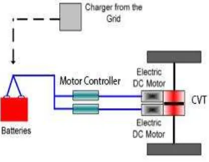
because the internal combustion engine was creating some problems. The causes of the problems are the emissions that produce from internal combustion are too high. When normal cars burn liquid fuels, such as petrol or diesel, it will produce pollution. This pollution is made up of poisonous gases (emissions) called greenhouse gases (GHGs) which can be harmful to the environment and to our health. These gases include carbon monoxide, oxides of nitrogen, carbon dioxide and methane. Carbon dioxide and greenhouse gases (GHGs) that dangerous can cause problems for our environment through processes such as the Greenhouse Effect or global warming. The green house effect can cause the earth become warm and warmer over a long period time. This is because the hot air is trapped in the earth. These are support by the higher gasoline prices, improvements in battery technology (transport.vic.gov.au, 2012). The electric vehicle (EV) is an automobile that is propelled by one electric motor or more by using the electrical energy which is stored in batteries or the other storage energy device. The function of electric motors to create strong and give electric cars instant torque while had a smooth acceleration (Sperling, 2009). The Figure 2.1 shows the schematic diagram of electric vehicle. The battery as voltage supplies the energy to the electric direct current (DC) motor to propel the car. The motor controller functions to control the voltage that needed in motor electric. The continuous variable transmission (CVT) functions as transmission to shift gear in electric vehicle.
2.2 TYPES OF ELECTRIC VEHICLE
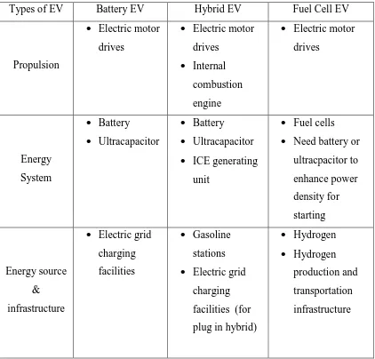
[image:24.595.109.531.362.766.2]The EV can divide into three types which are Battery electric vehicle (BEV), Hybrid electric vehicle (HEV) and Fuel Cell electric vehicle (FCV). BEV is a type of EV that used chemical energy stored in battery packs. BEV used electric motor and motor controls for propulsion instead of ICE. HEV is a combination of ICE propulsion system and electric propulsion system. HEV also had a better fuel economy and performance compared to the ICE. HEV also can functions as EV as well. FCV is a type of electric which use hydrogen. It uses fuel cell to produce electricity. Then, electricity will supply power to an electric motor using hydrogen and oxygen from the air.The Table 2.1 below shows the comparison between these three electric vehicles (Chan, 2007):
Table 2.1: Comparison between electric vehicles
Types of EV Battery EV Hybrid EV Fuel Cell EV
Propulsion
Electric motor drives
Electric motor drives
Internal combustion engine
Electric motor drives Energy System Battery Ultracapacitor Battery Ultracapacitor ICE generating
unit
Fuel cells Need battery or
ultracpacitor to enhance power density for starting Energy source & infrastructure
Electric grid charging facilities
Gasoline stations Electric grid
charging facilities (for plug in hybrid)
Hydrogen Hydrogen