REACH 2006, Penang, Malaysia
[Type text]
Abstract-This paper described the design, simulation and fabrication of the microstrip patch antennas at 2.4 GHz using one element, arrays 2 elements and four elements. The antennas have been modeled using microstrip lines and S parameter data from individual single element. The data is extracted from the simulation and combined with the microstrip transmission line. The properties of antennas such as bandwidth return loss and voltage standing wave ratio (VSWR) have been investigated and compared between simulation and measurements. Furthermore, the return losses of the antennas are below -10 dB from both simulation and measurement.
Index Term- Antenna, microstrip, microwave, patch, telecommunication.
I. INTRODUCTION
N today’s aircraft and spacecraft applications where the antenna’s size, weight, cost, performance, ease of installation and aerodynamic profile are of utmost consideration, conventional antennas are not suitable for today communication application. The term ‘Microstrip’ actually refers to any type of opens wave guiding structure which is not only a transmission line but also used together with other circuit components like filters, couplers, resonators, etc. A microstrip antenna in its simplest configuration consists of a radiating patch on one side of a dielectric substrate, which has a ground plane on the other side. The patch conductors usually made of copper or gold can be virtually assumed to be of any shape. However, conventional shapes are normally used to simplify analysis and performance prediction. The radiating elements and the feed lines are usually photo etched on the dielectric substrate.
The purpose of this design is to overcome several problems that occur with nowadays normal antennas. Importantly is to overcome the narrow bandwidth that the main problem of microstrip antenna[1]. Antenna that are using the microstrip are also very small in size but capable to radiate an ultra high frequency (UHF). It’s also build from a though substrate that makes it strong and stable from any high structure impact (e.g.: being drop from high places). Since it is small, it’s also low in weight, low in cost and easy to manufacture.
II. DESIGN AND DEVELOPE
Review Stage the design principle for the antenna arrays using microstrip technology requires patch, transmission line and new characteristic impedance dimension calculations. A single element of rectangular or square geometry as shown in Fig. 1 can be designed for the lowest resonant frequency using transmission line model.
The value of L, W and Wo can be found through equations in [2]. Calculation of design parameters for the single element, 2- and 4-elements with same resonant frequencies antennas using microstrip technology are shown in Table I[3]. The substrate used is FR4 with dielectric constant of 4.7 and height of 1.6 mm. The loss tangent of material is 0.019. Each antenna array has been simulated through simulation using Microwave Office.
TABLE I
DESIGN PARAMETER BETWEEN 3 ANTENNA ARRAY
TYPE L (mm) W (mm) Lo (mm) Wo (mm) 1 ELEMENT 27.90 36.27 16.51 2.91
2 ELEMENTS
29.00 38.50 16.00 2.00 4
ELEMENTS 29.00 37.00 16.00 2.20
A. Physical Structure
Fig. 1. Microstrip patch antenna with line feed
2.4 GHz Microstrip Antenna
Arrays
Abdul Rani Othman
, Chairulsyah Wasli, Mohd Riduan Ahmad
I
L
Lo
REACH 2006, Penang, Malaysia
Fig. 2. Schematic diagram antenna 1 element
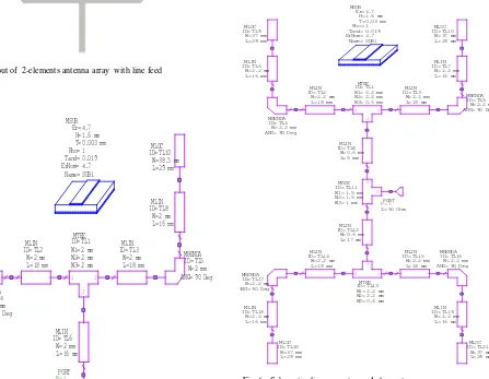
Fig. 3. Layout of 2-elements antenna array with line feed
1 2
Fig. 4. Schematic diagram antenna 2 elements
Fig. 5. Layout of 4-elements antenna array with line feed
1 2
TL15 MBENDA
ANG=
REACH 2006, Penang, Malaysia
[Type text]
(a)
(b)
(c)
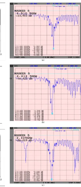
Fig. 7. Simulation output graph of Return loss (S11) and VSWR
(a) 1 element, (b) 2 elements, (c) 4 elements respectively
C. Measurement
(a)
(b)
(c)
Fig. 8. Measurement output graph of Return loss (S11) (a) 1 element,
(b) 2 elements, (c) 4 elements respectively
REACH 2006, Penang, Malaysia
[Type text]
diagram in Microwave Office as Fig. 4 . The 4 elements antenna is structured as Fig. 5 with using dimension from Table I, and it’s schematic diagram shown in Fig. 6.
III. RESULT AND DISCUSSION
A. Simulation and Measurement
The simulation result of those antennas are presented in Fig. 7 where they are compared the Return Loss and their VSWR. The development of the antenna was using the data from Table I to get the physical antenna look like Fig 1, Fig. 3 and Fig. 5. by etching and soldering of feed point process. Chose best sample from 3 samples developed then measure using Advantest Network Analyzer model R3767CG. The measurement result is shown in Fig. 8 respectively for 1, 2 and 4 elements..
B. Return Loss and VSWR comparison
The simulation and measurement result of return loss for the single element, 2 and 4 elements antennas with and different center frequency are shown in Table II. The resonance of the antennas can be seen by observing the lowest curve in the return loss. There is a close agreement between the simulation and measurement result for the bandwidth return loss except for the four array patches. From this research found that four array patch antenna give the best performance in return loss and VSWR compare to the others.
C. Differences
The result differences in resonant frequencies this may happened due to improper transmission line matching or improper etching process or line feed pointing process.
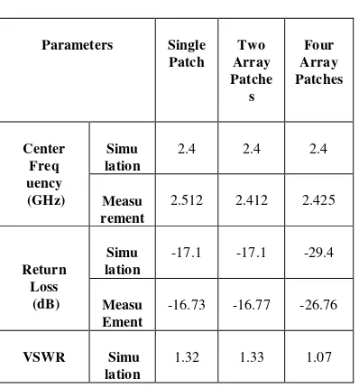
TABLE II
COMPARISON BETWEEN SIMULATION AND MEASUREMENT TEST
Parameters Single
Patch Two Array Patche s
Four Array Patches
Center Freq uency (GHz)
Simu lation
2.4 2.4 2.4
Measu rement
2.512 2.412 2.425
Return Loss (dB)
Simu lation
-17.1 -17.1 -29.4
Measu Ement
-16.73 -16.77 -26.76
VSWR Simu
lation
1.32 1.33 1.07
IV.CONCLUSION
In this paper, antennas using one, two and four elements has been designed, simulated, fabricated, and tested successfully. The physical dimension of the antennas is shown in Table I, and the result of simulation and measurement is shown in Table II. The four patch array antenna give best performance compare to the other. A bandwidth return loss below than -10 dB is achieved successfully.
REFERENCES
[1] Girish Kumar and K.P. Ray, “Broadband Microstrip Antenna”, Artech House, Inc., 2003
[2] Constantine A. Balanis, “Antenna Theory, Analysis and Design”, Third Edition, John Wiley & Sons, Inc, 2006, pg. 722 – 759.
[3] David M. Pozar, “Microwave Engineering”, Second Edition, John Wiley
and Sons, Inc., 1998