EFFECT OF BINDER AND FILLERS RATIO ON THE PROPERTIES OF
GRAPHITE/CARBON BLACK/EPOXY COMPOSITE FOR BIPOLAR
PLATE
TENGKU ASMAZATUL ADAWIAH BINTI TENGKU ABDUL KADIR B041210124
BMCS
Email: [email protected]
Final Report Projek Sarjana Muda
Supervisor: DR. MOHD ZULKEFLI BIN SELAMAT
Faculty of Mechanical Engineering Universiti Teknikal Malaysia Melaka
FINAL YEAR PROJECT
EFFECT OF BINDER AND FILLERS RATIO ON THE PROPERTIES OF
GRAPHITE/CARBON BLACK/EPOXY COMPOSITE FOR BIPOLAR
PLATE
NAME : TENGKU ASMAZATUL ADAWIAH BINTI TENGKU
ABDUL KADIR NO.MATRIX : B041210124
COURSE : BMCS
ii
SUPERVISOR DECLARATION
“I hereby declare that I have read this thesis and in my opinion this thesis is sufficient in terms of scope and quality for the award of the Bachelor of Mechanical
Engineering (Structure & Materials)”
iii
DECLARATION
“I hereby declare that this report is my only own work except for the summaries and article that each of that I already cited in the references”
Signature : ... Author : TENGKU ASMAZATUL ADAWIAH BINTI
iv
ACKNOWLEDGEMENT
First of all, I would like to express a lot of thank to Allah S.W.T for giving me strength to completely finish my final year project successfully. I would like to express my gratitude to my advisor, Dr. Mohd Zulkefli Bin Selamat for his guidance, support, encouragement, and inspiration during the course of my degree studies. His patience and kindness are greatly appreciated. May Allah S.W.T bless him in this world and hereafter. My final year thesis would not have been possible done it without invaluable guidance and helping from those experiences. His valuable, suggestion and encouragement enabled me to handle all the tasks of this enormity with confidence. He is the best Supervisor that I ever had.
I am indebted to many people who have been helping me to undergo my final year project period where the presences are the essence to make my training successful. They are people of my respects who involve directly or indirectly throughout this project.
v
Not to forget all of the faculty of Mechanical Engineering’s staff members for guiding me and rendered their help during the period of my final year project.
vi
ABSTRACT
vii
ABSTRAK
viii
CONTENTS
CHAPTER TITLE PAGE
SUPERVISOR DECLARATION ii
DECLARATION iii
ACKNOWLEDGEMENT iv
ABSTRACT vi
ABSTRAK vii
CONTENTS viii
LIST OF TABLES xi
LIST OF FIGURES xii
LIST OF ABBREVIATIONS xiii
CHAPTER 1 INTRODUCTION 1
1.1 Background 1
1.1.1 Working principles of PEMFC 2 1.1.2 Functions of Bipolar Plate 3
1.2 Problem Statement 4
1.3 Objectives 5
1.4 Scope 5
CHAPTER 2 LITERATURE REVIEW 6
2.1 Overview of Literature Review 6
2.2 PEM Fuel Cells 6
ix
CHAPTER TITLE PAGE
2.3 Bipolar Plate 9
2.3.1 Requirements of the Bipolar Plates 9 2.3.3 Types of Bipolar Plates 10
2.3.3.1 Electro-graphite Bipolar Plates 10 2.3.3.2 Metal bipolar plates 11 2.3.3.3 Polymer Composite Bipolar Plates 11
2.4 Graphite 12
2.5 Carbon Black 13
2.6 Epoxy Resin 14
2.7 Processing Method 15
2.7.1 Compression Moulding 15 2.7.2 Injection Moulding 17
2.8 Testing 18
2.8.1 Electrical Conductivity Testing 18 2.8.2 Flexural Strength Testing 19 2.8.3 Measurement of Density Properties 20
CHAPTER 3 METHODOLOGY 21
3.1 Experimental Overview 21
3.2 Materials Selection 22
3.3 Fabrication Method 23
3.3.1 Characterization of Raw Material 23
3.3.2 Methods 23
3.4 Taguchi Method 24
3.5 Pre Mixing Raw Material 27
3.6 Mixing Process 28
x
3.8.1 Electrical Conductivity 30
3.8.2 Density Testing 32
3.8.3 Flexural Strength 33 3.8.4 Shore Hardness Measurement 33
CHAPTER 4 RESULT 34
4.1 Preliminary Work 34
4.2 Orthogonal Array 36
4.3 Experimental Result Based In Taguchi Method 38 4.4 Optimization Parameter Used In Taguchi Method 39
4.5 Result Of Optimize Sample 43
CHAPTER 5 DISCUSSION 45
5.1 Discussion 45
5.1.1 Result of Previous Research 2013 45 5.1.2 Result of Previous Research 2014 46 5.2 Comparisons between Previous and Latest 47
Research
5.2.1 Electrical Conductivity 48
5.2.2 Bulk Density 48
5.2.3 Shore Hardness 49
CHAPTER 6 CONCLUSION & RECOMMENDATION 50
6.1 Conclusion 50
6.2 Recommendation 52
REFERENCES 53
APPENDICES 55
xi
LIST TABLES
NO TITLE PAGE
2.1 Primary components of a PEM fuel cell (Wang, 2006). 8 2.2 Requirement properties of the bipolar plate (DOE target) 10 3.1 Material property of Graphite (Gr), Carbon Black (CB) and 23
Epoxy (EP). (Selamat, 2013)
3.2 The compression molding factors for three levels Taguchi 26 Design.
3.3 Orthogonal array in Taguchi Design 27 4.1 Comparison between Previous Researches 34 4.2 Formation of the Weight Percentage Ratio (%) of the Materials 35 4.3 Formation Composition of Materials 36 4.4 The compression moulding factors for three levels Taguchi 37
Design
4.5 Orthogonal array in Taguchi Design 37
4.6 Parameters of each Sample 38
4.7 Mean of Electrical Conductivity Testing of Each Sample 40 4.8 Optimization Parameter in Taguchi Design 43 4.9 Electrical Conductivity of Optimization Sample 44 4.10 Bulk Density of Optimization Sample 44 4.11 Shore Hardness of Optimization Sample 44 5.1 Result of Electrical Conductivity, Bulk Density and Shore 46
Hardness Testing in 2013
5.2 Result of Electrical Conductivity, Bulk Density and Shore 47 Hardness Testing in 2014
xii
LIST FIGURES
NO TITLE PAGE
1.1 Schematic of Proton Exchange of Membrane Fuel Cell. 2 (Haile, 2003)
2.1 Polymer Electrolyte Membrane Fuel Cell 8 (Beth, 2009).
2.2 Compression molding processes for bipolar plates 16 (Rungsima et. al.).
2.3 Injection molding processes for bipolar plates 18 (Rungsima et. al.).
2.4 Schematic diagram of the in-plane electrical conductivity 19 measurement. (Jong, 2010)
2.6 Three-point loading flexural strength. (Reza, 2011) 19 3.1 Flow chart of the methodology process. 22 3.2 The materials for mixing process (a) Graphite, (b) Carbon Black, 23
(c) Epoxy Resin and Hardener.
3.3 Ball Mill Machine Model 2VS 28
3.4 Mixing process by using high speed mixer 29 3.5 Motorise Hydraulic Moulding Test Press 30 3.6 Jandel Multi Height Four Point Probe 31
3.7 Electronic Densimeter Machine 32
3.8 Instron Machine 33
3.9 Shore Hardness Tester 33
4.1 ` Taguchi Analysis with all the Factors Level 41
4.2 Main Effects Plot for Means 42
4.3 Main Effects Plot for SN Ratios 42
xiii
LIST OF ABBREVIATIONS
PEMFC - Polymer Electrolyte Membrane Fuel Cell U.S.D.O.E - United States Development of Energy Gr - Graphite
CB - Carbon Black
1
CHAPTER I
INTRODUCTION
1.1 BACKGROUND
2
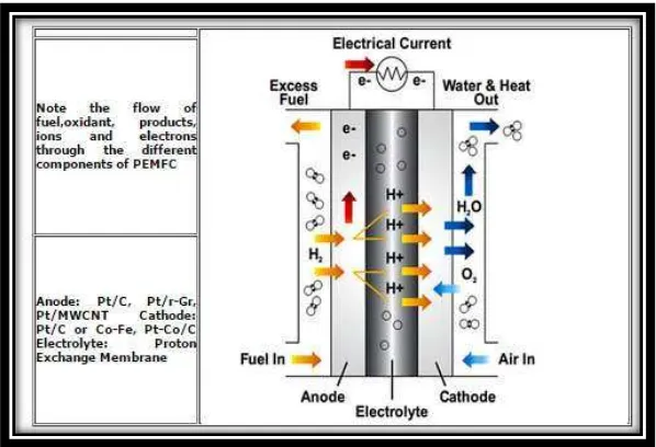
Figure 1.1 Schematic of Proton Exchange of Membrane Fuel Cell (Source: Haile, 2003)
1.1.1 Working principles of PEMFC
A polymer electrolyte membrane fuel cell (PEMFC) is a good contender for portable and automotive propulsion applications because it provides high power density, solid state construction, high efficiency chemical-to-electrical energy conversion, near zero environmental emissions, low temperature operation (50 -100 C), and fast and easy start up. The U.S. Department of Energy (DOE) has also identified the PEMFC as the alternative candidate to replace the internal combustion engine in transportation applications. However, barriers to commercialization remain a major problem. The fundamental and technical understanding of the bipolar plate fabrication is the main challenge in the commercialization of PEM fuel cells. Other challenges include manufacturing and material costs, material durability and reliability, and hydrogen storage and distribution issues. One of the major factors limiting fuel cell is the development of the bipolar plates, which are one of the
PEMFC’s key components. The requirements of the bipolar plate characteristic pose
3
1.1.2 Functions of Bipolar Plate
Therefore, research in materials, designs and fabrications of bipolar plates for PEMFC applications is a crucial issue for global commercialization. The main functions of bipolar plates in the PEMFC are to distribute the process gases (hydrogen and oxygen) to the positive and negative electrode respectively within the cell, to separate the individual components of fuel cells, and to carry the current away from the cell, (Weil, 2004; Mighri, 2004). In order to prepare for a commercialization, the bipolar plate must meet the design requirements such as high electrical conductivity, efficient gas tightness, low permeability, good chemical stability, high corrosion resistance, low volume and high thermal conductivity, and lightweight and acceptable mechanical strength, such as withstanding the stack clamping force. The optimal bipolar plate criteria include low cost, reproducibility, and easy finishing and recyclable (Cunningham, 2005; Blunk, 2006; Krupa, 2004; Thongruang, 2001).
Currently, the most promising material for mass production of bipolar plate is pure Gr material. However, it is very brittle and difficult to machine to fulfill the specifications needed for fuel cell stacks. Other materials such as metal-based require proper machining process, need special coating, have the extra weight and have a high tendency to corrode even though they have good electrical conductivity. Similarly, carbon-based materials have poor electrical and thermal conductivity, fragile structure and low mechanical strength even though they are easy to form (Acosta, 2006; Ezquerra, 2001; Zou, 2002).
4
plate. Graphite powder is the most commonly used material for a bipolar plate. Graphite has a good electrical conductivity and excellent corrosion resistance with a low density of about 2 g . However, it lacks mechanical strength and has poor ductility. The carbon black powder is introduced to the graphite composite in order to improve the properties of the composite. Epoxy will be used as the binder in this composite.
1.2 PROBLEM STATEMENT
5
probes and flexural strength was measured using three point test according to ASTM D638. The result from the tests will be analyzed whether the properties of conductive composite were achieved and meted be DOE requirement.
1.3 OBJECTIVES
This project is to study the effect of binder and filler ratio on the electrical and mechanical properties of Graphite (Gr) /Carbon Black (CB) /Epoxy (EP) composite for bipolar plates. The filler materials are graphite and carbon black as second filler whereas the epoxy as the binder. The main objectives are:
Study the effect of binder and filler ratio of the properties of Gr/CB/EP composite.
Determine the suitable loading in Gr/CB/EP composite.
1.4 SCOPE
6
CHAPTER 2
LITERATURE REVIEW
2.1 OVERVIEW OF LITERATURE REVIEW
This chapter will present the review of bipolar plate in a fuel stack. The review is from the recent and past journals, technical papers, and reference books have been studied to understand the related topic area of this project. Plus, this chapter will go through deeply regarding bipolar plate such as its background, fabrication, and testing used in order to know the properties of the bipolar plate.
2.2 PEM FUEL CELLS
2.2.1 Basic Principles of PEM Fuel Cells
7
Anode side :
Cathode side : Net reaction :
The pressurized hydrogen gas (H2) entering the fuel cell on the anode side. This gas is forced through the catalyst by pressure. A H2 molecule splits into two H+ ions and two electrons (e-) after it comes in contact with the platinum on the catalyst. The electrons are conducted through the anode, where they make their way through the external circuit, e.g., a turning motor, and return to the cathode side of the fuel cell. Meanwhile, on the cathode side of the fuel cell, oxygen gas (O2) is being forced through the catalyst, where it forms two oxygen atoms. Each of these atoms has one pair of electrons and attracts the two H+ ions through the membrane, where they combine with two of the electrons from the external circuit to form a water molecule (H2O). This reaction in a single fuel cell produces only about 0.7 volts of electric energy. To get this voltage up to a reasonable level, many separate fuel cells must be combined to form a fuel-cell stack.
PEMFC’s operate at fairly low temperatures (~ 80°C), which means they warm up quickly and do not require expensive containment structures. Constant improvements in the engineering and materials used in these cells have increased the power density to a level where a small size device can power a car.
2.2.2 Components of PEM Fuel Cell Stack
8
Figure 2.1: Polymer Electrolyte Membrane Fuel Cell (Source: Beth , 2009)
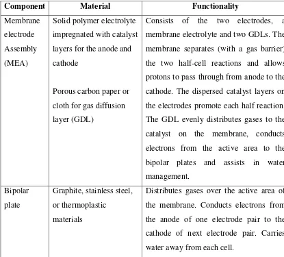
Table 2.1: Primary components of a PEM fuel cell (Source: Wang, 2006)
Component Material Functionality
Membrane electrode Assembly (MEA)
Solid polymer electrolyte impregnated with catalyst layers for the anode and cathode
Porous carbon paper or cloth for gas diffusion layer (GDL)
Consists of the two electrodes, a membrane electrolyte and two GDLs. The membrane separates (with a gas barrier) the two half-cell reactions and allows protons to pass through from anode to the cathode. The dispersed catalyst layers on the electrodes promote each half reaction. The GDL evenly distributes gases to the catalyst on the membrane, conducts electrons from the active area to the bipolar plates and assists in water management.
Bipolar plate
Graphite, stainless steel, or thermoplastic
materials
[image:22.595.107.522.394.769.2]9
Endplate Material with good mechanical strength (normally steel or aluminum)
Provides integrated assembly for the entire fuel cell stack.
Current collector
Metal material with good electric contact and conductivity, normally copper.
Collects and transfers the current from the stack to an external circuit.
2.3 BIPOLAR PLATE
According to Lee et. al., (2009), bipolar plate can categorized as the major components in PEMFC where it consists of huge portion of the stack volume and cost. Bipolar plate can either comesfrom metal based, graphitic based or polymer composite. For a commercialization, bipolar plate must meet the design requirement that had been listed by Department of Energy (DOE). The optimal bipolar plate criteria should include all the requirements such as low cost, easy finishing and reproductivity.
2.3.1 Requirements of the Bipolar Plates
10
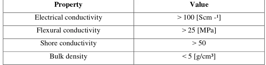
Table 2.2 Requirement properties of the bipolar plate (DOE target)
Property Value
Electrical conductivity 100 [Scm -¹] Flexural conductivity 25 [MPa]
Shore conductivity 50
Bulk density 5 [g/cm³]
2.3.2 Types of Bipolar Plates
There are many materials and methods for manufacture of bipolar plates. The most promising types and manufacturing methods of bipolar plates are described below.
2.3.2.1 Electro-graphite Bipolar Plates