DOI: 10.12928/TELKOMNIKA.v15i2.6108 718
Parametric Analysis of Wearable Vialess EBG
Structures and Its Alication for Low Profile Antennas
Adel Y.I. Ashyap*1, Zuhairiah Zainal Abidin2, Samsul Haimi Dahlan3, Huda A. Majid4, Zuraidah Muhammad5, Muhammad Ramlee Kamarudin6
1,2,3,4,5
Research Center of Alied Electromagnetics, Faculty of Electrical and Electronic Engineering
Universiti Tun Hussein Onn Malaysia (UTHM), Batu Pahat, Johor, Malaysia, 81310, Skudai, Johor, Malaysia
6
Wireless Communication centre (WCC) Faculty of Electical Engineering, Universiti Teknologi Malaysia (UTM), 81310, Skudai, Johor, Malaysia
Cooresponding author, e-mail: [email protected]*1, [email protected]2, [email protected]6
Abstract
Electromagnetic Bandgap (EBG) structures are one class of metamaterial with attractive properties that unavailable in nature and widely used for improving the electromagnetic performance. Its In-phase reflection frequency band is indicated as operation frequency band, whose characteristic is closely related to the parameters of EBG structure, such as patch width (w), gap width (g), substrate height (h) and substrate permittivity (ε). The presence of via within EBG structure is associated with design and fabrication complexities, which led the researchers to study uniplanar EBG. These structures require no via and can easily be fabricated and integrated with RF and microwaves alication. Therefore, an investigation study on the effect of the parameters of the vialess EBG surface and some design guidelines have been obtained. An example of an antenna integrated with EBG is also studied. The result indicates that the EBG ground plane significantly improves the work efficiency of the antenna in a particular frequency band.
Keywords: AMC, EBG, Rflection phase, Electromagnatic BandGap
Copyright © 2017 Universitas Ahmad Dahlan. All rights reserved.
1. Introduction
In the latest years, there has been a great deal of interest in the area of electromagnetic bandgap (EBG) engineering. EBG has been widely used for enhancing the electromagnetic performance [1-5] due to its capability to influence the propagation of electromagnetic waves to a level that was impractical before. Moreover, it can produce a wide variety of design alternatives for researchers working in the area of RF, microwave and photonics or as a part of them to improve their efficiency especially in antenna design which suffers from surface wave [6-8].
aropriate frequency regions. The first frequency region is corresponding to the quadratic-phase reflection coefficient (90o±45o), where the structure produces good return loss. The second frequency region is corresponding to the in-phase reflection coefficient (+90oto −λ0o), where the EBG structure radiates in-phase rather than out of phase as in the PEC case, and it has zero degrees at the resonant frequency [9-13]. The used of vialess EBG helps to avoid complexities, implementation and more suitable for thin substrate material which makes the fabrication easier [1]. In this paper, the effects of the parameters of wearable vialess EBG are investigated and an example of EBG structure for wearable alications is discussed.
2. EBG Unit Cell Design And Optimization
The unit cell of EBG substrate is designed in two steps. The first step is using Sievenpiper’s equations [14] and second is using Computer Simulation Technology (CST) to optimize and verify the design structures.
2.1 Sievenpiper’s Equations
There is no exists precise formula that can express the impedance nature of an EBG except the following equations which called Sievenpiper equations:
r 0h (1)
(2)
(3)
where 0 and 1 are the permeability and permittivity of free space respectively, meanwhile r
and 2 is the relative permeability and relative permittivity of the substrate, respectively. g is the
gap width between adjacent cells; W is the patch width, and h is the thickness of the substrate. Since this paper focuses on wearable alication for body area network (BAN) at 2.4 GHz, a denim fabric is chosen as dielectric with relative permittivity of 2.3405 and thickness of 2.1 mm. By using the dielectric properties and alied in Equation (1) the inductance has values of 2.6389 n H. In order to calculate the width, W from Equation (2), the capacitance first needs to be found by rearranging Equation (3) which has value of . Unfortunately, in Equation (2) there are still two unknown variables which are the width (w) and gap (g) and the only equation related between capacitance, patch width (W). Therefore, the gap is assumed to be 2mm in order to find a reasonable solution of W which is 45.79 mm.
2.2 Modeling in CST
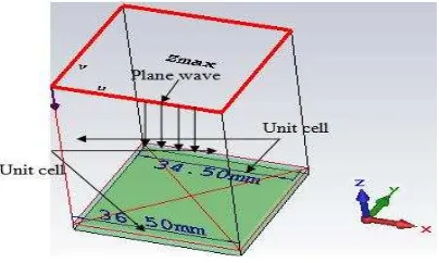
The calculated value from the Sievenpiper equations and the method Finite-difference frequency-domain (FDFD) is alied to analyze the EBG structure using CST with boundary condition of unit cell in x and y while PEC at Zmin and open Zmax as depicted in Figure.1.
Figure 2 shows the reflection phase of the EBG based on Sievenpiper equations. It is observed that the cross zero resonant frequency is at 1.867 GHz which is lower than the desired frequency. This is due to the simplicity of the equation. However, the result is close enough to be used as initial conditions for the CST optimizer.
Since the desired frequency in this paper is 2.4 GHz, an optimization is used. In order to relate the optimization and Sievenpiper equations, the width parameter is selected for optimization as shown in Figure 3. It is seen that the desired frequency can be achieved when w=34.5 mm. The different percentage between Sievenpiper equations and optimization is calculated in Equation (4). The finalize dimension of the EBG unit cell is listed in Table 1 as reference value to perform the parametric study and to obtain guidelines that help the designer to consider before designing.
(4)
Figure 2. Reflection Phase based on the calculation
Figure 3. Reflection Phase based on the optimization
Table 1. The Optimized Dimention of EBG Unit Cell
3. Parametric Analysis of the Unit Cell of Ebg Structure
Electromagnetic characteristics of an EBG structure are found by its physical dimensions. The unit cell of EBG structure shown in Figure 1 are affected by four main parameters namely, patch width (w), gap width (g), substrate height (h), and substrate permittivity ( ) as shown Figure 4. In this part, the effects of these parameters are studied one by one in order to obtain some guidelines for EBG surface designs.
(a) Top view (b) Side view
Figure 4. EBG vialess structure (a) top view (b) side view Parameters Value(mm)
w 34.5 g 2
3.1. Square Patch Width Effect (w)
Patch width acts as an important role in controlling the frequency band. To investigate the effects of the unit cell of EBG patch width, other parameters are kept the same as in Table 1 while the patch width is varied from 25 mm to 37 mm. Figure 5 shows the observed reflection phases of a unit cell of EBG surfaces with varies patch widths. It is noticed that the resonant frequencies corresponding to 0o decrease when the patch width is increased. Moreover, the curve slope near the resonance becomes steep, which points to a narrow bandwidth corresponding to ±90o [11]. This behavior can be explained using the lumped LC model. By referring to Equation (2) the increase in patch width leads to increase in capacitance which decreases the resonant frequency as in Equation (3) and therefore, the bandwidth becomes narrow.
Figure 5. Investigation on patch width effect on unit cell EBG reflection phase
3.2. Gap Width Effect (g)
The gap width determines the coupling effect of each EBG unit with the other neighbor cells. Therefore, the resonant frequency of the unit cell of EBG surface is also affected by varying the gap width. Through this study, the others parameters kept constant as in Table 1 while the gap width is changed from 0.5 mm to 3 mm. Figure.6 shows the reflection phases of EBG surfaces with different gap widths. It is seen that as the gap width is increased, the resonant frequency of the in-phase reflection coefficient also increased. Meanwhile, the curve slope near the resonance frequency becomes flat, which shows a large bandwidth. Additionally, it is realized that the gap width of the EBG has an oosite effect on the patch width. This can be clarified by the lumped LC model where by increasing the gap width will decrease the capacitance value result, hence, increasing both the resonant frequency and the bandwidth.
Figure 6. Investigation on gap width effect on unit cell EBG reflection phase
3.3. Substrate Height Effect (h)
kept constant as maintained in Table 1. It is preferable in practical alications that the height of substrate of EBG surface is to be small compared to the wavelength. Figure 7 displays the reflection phase with different heights of the EBG surface substrate. It is observed that as the height of the substrate increased, the resonant frequency decreases. This is similar to the effect of the patch width. Nevertheless, the curve slope of the reflection phase becomes flat which indicates an increasing in the bandwidth with the substrate height. This is similar to the effect of the gap width of the EBG surface. This can be described by the LC model. When the substrate height is increased causes the equivalent inductance, L to increases while the capacitance remains unchanged. Hence, the resonant frequency shifts to low but the bandwidth increases. From a designer viewpoint, adjusting the substrate height has a special advantage in decreasing the resonant frequency whereas increasing the bandwidth.
Figure 7. Investigation on substrate height effect on unit cell EBG reflection phase
3.4. Substrate Permittivity Effect (ɛ)
Substrate permittivity is another effective parameter used to determine the resonant frequency. Since this paper focus only on wearable alications, commonly substrate fabric materials such as felt, jeans, denim, and PDMS are used to study. The unit cell of EBG structure investigated here has the same parameters as in Table 1 except that the permittivity is varied. The reflection phases of a unit cell of EBG surfaces with several permittivities are shown in Figure 8. It is observed that the higher the relative permittivity of a unit cell of the EBG substrate the lower is the resonant frequency so does the bandwidth. Therefore, to reduce the size of the unit cell of EBG surface high dielectric constant substrate is used but the price will pay the narrow bandwidth.
Figure 8. Investigation on substrate permittivity effect on unit cell EBG reflection phase
the designer will have a view of the effects of each parameters that will help him to design base on the demand of his alication.
4. Alication of the Ebg Structure for Low Profile Antenna
It is preferable in wireless communications to have low profile antennas which typically refers to the antenna structure whose overall height is less than one tenth of the wavelength at the working frequency. To avoid destructive interference between the radiated wave and the reflected wave from the reflecting surface, the antenna must be placed at a distance of quarter wavelength ( 0/4) when a Perfect Electric Conductor (PEC) ground plane is used as a reflector
as shown in Figure 9(a). To reduce the height of the antenna, an EBG surface is used; therefore, the antenna can be placed very close to the EBG without worrying about the reflected waves causing destructive interference and maintain low profile design as shown in Figure 9(b) [14-17].
The antenna is placed upon an ordinary metal ground plane. The overall size of antenna is 40 x 20 x 0.7 mm3 and the distance between the antenna and the ground plane is 3.1 mm. The same antenna is placed over an EBG structure with 3 x 3 units and the same dimension in Table 1. The overall heights of two cases are the same, so the distance between the antenna and the EBG uer surface is 1mm. The input impedance is matched to a 50Ω transmission line.
(a) (b)
Figure 9. (a) The microsrip antenna with traditional metal ground plane.(b) The microsrip antenna with EBG ground planes
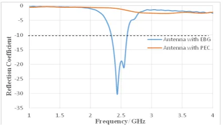
Figure 10 shows the reflection coefficient of the antennas, evaluated by S11 parameters. It is observed that when the antenna is place over EBG ground plane, it has better reflection loss compared to the PEC ground plane. This is due to the image current on the PEC which is in a reverse direction to the antenna current. This result a destructive effects that impedes the efficiency of the radiation of the antenna. Besides that, EBG has an image current in-phase rather than out of phase with the antenna current result in constructive effect and can be varies from ±180° which successfully serves as the ground plane of the antenna with low profile, low return loss and high radiation efficiency.
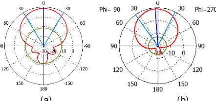
Figure 11 shows the radiation pattern of the antenna of the twocases. It is observed that when the antenna is placed over EBG, a higher front to back ratio and very low back lobe compared to other cases. Besides that, a higher gain of 9.1 dBi is noticed when the antenna is place over EBG compared to the antenna without EBG and antenna with PEC. This is due to that the EBG surface is capable of providing a constructive image current within a certain frequency band. This current will add with original current of the antenna. The combinations of these current resulting in improve the front to back ratio as well the gain besides that EBG has the ability to suress surface wave.
(a) (b)
Figure 11. Radiation patterns of the antenna (a) with PEC (b) with EBG
5. Conclusion
A comprehensive investigation on the effect of the parametric study on the vialess EBG such as patch width (w), gap width (g), substrate height and substrate permittivity of the EBG operating frequency band, with some guidelines for an EBG surface. In addition, the antenna is studied with different ground places: ordinary metal and EBG surface. The results show that the EBG greatly improve the antenna performance such as front to back radiation and gain compares to ordinary metal. Therefore, the EBG structure has a good alication as ground, and it is valuable to do a parametric study on EBG design.
Acknowledgement
The authors of this paper wish to acknowledge the funding of this project by Ministry of Education Malaysia (MOE) under Research Accularation Collaborative Effort (RACE) Vot No. 1510 and Vot GUP UTM (00M69).
References
[1] S Zhu, R Langley. Dual-band wearable textile antenna on an EBG substrate. IEEE Trans. Antennas Propag. 2009; 57(4): 926–935.
[2] Abhari R, Eleftheriades GV. Metallo-dielectric electromagnetic bandgap structures for suression and isolation of the parallel-plate noise in high-speed circuits. IEEE Trans. Microw. Theory Tech. 2003; 51(6): 1629–1639.
[3] R Dewan, S Rahim, S Ausordin, T Purnamirza. The Improvement Of Array Antenna Performance With The Implementation Of An Artificial Magnetic Conductor (Amc) Groundplaneandin-Phase Superstrate. Progress In Electromagnetics Research. 2013; 140: 147-167.
[4] G Josefa, A Tayebi, C Felipe. Design and Optimization of an EBG Antenna with an Efficient Electromagnetic Solver e Ram on. 2012.
[5] P Kovács, T Urbanec. Electromagnetic band gap structures: Practical tips and advice for antenna engineers. Radioengineering. 2012; 21(1): 414–421.
[6] Li Yang, M Fan, F Chen, J She, Z Feng. A Novel Compact Electromagnetic–Bandgap (EBG) Structure and Its Alications for Microwave Circuits. IEEE Transaction on Microwave Theory and Techniques. 2005; 53(1).
[7] J Liang, HYD Yang. Microstrip Patch Antennas on Tunable Electromagnetic Band-Gap Substrates. IEEE Transaction on Microwave Theory and Techniques. 57(6): 2009.
[9] M Elayachi, P Brachat, P Ratajczak. EBG identification by the Reflection Phase Method (RPM) design for alication wifi antenna. Eur. Sp. Agency, (Special Publ. ESA SP). 2006; 626 SP.
[10] O Ayop, MKA Rahim. Analysis of mushroom-like electromagnetic band gap structure using suspended transmission line technique. IEEE Int. RF Microw. Conf. RFM 2011 - Proc. 2011; 258–261.
[11] G Saleh. High Impedance Surface – Electromagnetic Band Gap (HIS-EBG) Structures for Magnetic Resonance Imaging ( MRI ) Alications. 2013.
[12] F Yang, Y Rahmat-Samii. Phase reflection characterizations of the EBG Ground plane for Low Profile Wire Antennas. IEEE Antennas Propag. Mag. 2003; 51(3): 2691.
[13] MS Alam, N Misran, B Yatim, MT Islam. Development of electromagnetic band gap structures in the perspective of microstrip antenna design. Int. J. Antennas Propag. 2013.
[14] Sievenpiper D. High-impedance electromagnetic surfaces, Ph.D.Thesis, University of California, Los Angeles. 1999.
[15] M Mantash, A Tarot, S Collardey, K Mahdjoubi. Dual-band CPW-fed G-Antenna using an EBG structure. 2010; 453–456.
[16] N Chahat, M Zhadobov, RSauleau, K Mahdjoubi. Improvement of the on-body performance of a dual-band textile antenna using an EBG structure. Loughborough Antennas and Propagation Conference, LAPC 2010. 2010: 465–468.