CERAMICS
INTERNATIONAL
Ceramics International 42 (2016) 6962–6968
Design and optimization of a wideband impact mode piezoelectric
power generator
A.A. Basari
a,n, S. Hashimoto
a,n, B. Homma
b, H. Okada
b, H. Okuno
b, S. Kumagai
b aDivision of Electronics and Informatics, School of Science and Technology, Faculty of Gunma University, 1-5-1 Tenjin-cho, Kiryu, Gunma 376-8515, Japan b
Research and Development Department, Mitsuba Corporation, 1-2681 Hirosawa-cho, Kiryu, Gunma 376-8555, Japan
Received 10 November 2015; received in revised form 24 December 2015; accepted 10 January 2016 Available online 15 January 2016
Abstract
This paper proposes a new design of an impact mode piezoelectric power generator that is able to operate in a wide frequency bandwidth by using a round piezoelectric ceramic as the energy converter. The evaluation results show that the output of the power generator can be optimized by implementing a so-called indirect impact configuration. To realize this type of configuration, a shim plate is placed between the piezoelectric ceramic and the hitting structure. At a certain base excitation frequency, the output efficiency of this configuration increases to about 4.3 times that of the direct impact configuration. Furthermore, it is demonstrated that the designated power generator is able to generate electric energy up to approximately 1.57 mJ within 120 s from the vibration of a moving vehicle.
&2016 Elsevier Ltd and Techna Group S.r.l. All rights reserved.
Keywords:Impact mode; Piezoelectric power generator; Wide operating frequency bandwidth; Shim plate
1. Introduction
The application of piezoelectric devices for electric energy generation from ambient mechanical vibration has been widely investigated by researchers for decades. The ability of the devices to become alternative power sources, especially for low power electronic devices in a state of vibration, has been discussed extensively in [1–6]. Piezoelectric devices generate electricity through the deformation of its structures. This deformation generates mechanical strain within its structure and thus induces electric energy. In the form of a cantilever beam, excitation of one end of the piezoelectric beam generates strain force all over the beam while it undergoes bending motion. This typical deformation technique for power generation by piezoelectric devices has also been discussed. To optimize the output of the piezoelectric device structure, several factors, such as the shape of the device [7–9], load impedance and resonant frequency[9,10]have been studied. In
most cases, piezoelectric devices with a cantilever beam perform very well at their resonant frequencies, whereas at other frequencies the output drops abruptly. Consequently, the operating frequency bandwidth of the device is small, and it is difficult to capture and convert the non-resonant vibration to electricity.
An alternative way of deforming piezoelectric devices is by applying mechanical forces through impact directly to the device. The force of the impact deforms the device and generates strain forces and subsequently the flow of charges. Studies have shown that one of the advantages of power generation by impact mode piezoelectric devices is their ability to operate in a relatively wider frequency bandwidth[11–14]. In these studies, it was shown that by limiting the displacement of the free end of a piezoelectric device with stoppers, a multi-stage stiffness device can be created. Consequently, a wider range of output is achievable in the frequency domain. Investigations of the mechanical impact mechanism on piezo-electric energy harvesting have also been reported in[15–17]. It was concluded that mechanical impact can also be an effective method for harvesting vibration energy with piezo-electric devices.
www.elsevier.com/locate/ceramint
http://dx.doi.org/10.1016/j.ceramint.2016.01.082
0272-8842/&2016 Elsevier Ltd and Techna Group S.r.l. All rights reserved. n
Corresponding authors.
In this paper, a new method of forced vibration-based piezoelectric power generation via mechanical impact is proposed. It is demonstrated experimentally that the designated power generator, which consists of a base beam, vibrating beam, spacers and piezoelectric device with an attached shim plate, is capable of operating in a wider frequency bandwidth with relatively high output power. Additionally, the application of the power generator in generating electric energy from a vehicle is presented.
2. Power generator concept and design
The proposed vibration-based power generator consists of three main structures, as shown in Fig. 1. They are the base beam, the vibrating beam and the spacers. The dimensions of these three structures are shown inTable 1. The base beam is the place on which the piezoelectric device will be fixed. As seen inFig. 1, the base beam has a round hole. The hole size was specifically set to 30 mm so that when the piezoelectric device is placed on the beam, the piezoelectric ceramic, which is 25 mm in diameter inside a brass plate 35 mm in outer diameter, will not be supported by the base beam. The purpose of this setup is to avoid incrementing the piezoelectric stiffness, which will reduce the magnitude of the outputs [17]. To reduce the effect of anti-resonance output, the thickness of the base beam is chosen to be 10 times that of the vibrating beam. The vibrating beam is the structure that
deflects and hits the piezoelectric device. One end of the vibrating beam is coupled to the base beam and the spacers. The other end of the beam is free andfixed with a proof mass and an iron tip. The proof mass serves as the deflection booster and the tip is the part that hits the piezoelectric device. Next, as specified by its name, the spacer was used to separate the base beam and the vibrating beam. The number of spacers determines the configurations of the power generator: the non-touching configuration or the pre-load configuration. Our analysis shows that by having a spacer thickness of 11.3 mm under the rest condition, the iron tip will lightly touch the piezoelectric device; we refer to this type of configuration as the pre-load configuration. Increasing the thickness of the spacer to 12 mm will produce a gap of approximately 0.42 mm between the iron tip and the piezoelectric device; we refer to this configuration as the non-touching configuration.
2.1. Impact configuration
As can be seen in Fig. 1(a), an aluminum shim plate is attached on top of the piezoelectric device. This shim plate is one of the main contributions of the study. Instead of hitting the piezoelectric device directly, the shim plate is placed between the tip and the device. The purpose of the shim plate in this impact configuration is to optimize the output of the piezoelectric power generator when the device is being hit. The experimental evaluation shows that this configuration signifi -cantly increases the output power of the power generator in comparison with that of the direct impact configuration.
The energy generation of the piezoelectric device in impact mode is given by Eq.(1), and its open circuit voltage is given by Eq. (2). The equations formulate the electric energy of the piezoelectric device in the d33mode.E,C,V,tandDrepresent the energy, capacitance of the device, open circuit voltage, thickness, and diameter of the piezoelectric device, respec-tively. The piezoelectric voltage constant is denoted by g33. Based on the equations, the external factor that influences the Fig. 1. Structure of the power generator, the base beam, and the piezoelectric device.
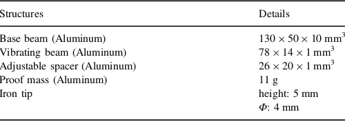
Table 1
Specifications of structures of the power generator.
Structures Details
Base beam (Aluminum) 1305010 mm3
Vibrating beam (Aluminum) 78141 mm3 Adjustable spacer (Aluminum) 26201 mm3
Proof mass (Aluminum) 11 g
Iron tip height: 5 mm
output of the piezoelectric device is the magnitude of forceF.
E¼CV2 ð1Þ
V¼4g33F
π t
D2
ð2Þ
By assuming that the shim plate is a cylinder, the force acting on the surface of the piezoelectric device is dependent on the indentation depth and the contact surface area. Let us analyze the contact configuration of a rigid cylinder with aflat end facing an elasticflat surface, as shown in Fig. 2. In this case, the piezoelectric device is assumed to be the elastic surface and the aluminum shim plate on the piezoelectric device is the rigid cylinder. The equation of force acting on the elastic surface is given by Eq. (3).
F¼2aYd ð3Þ
whereais the contact radius,dis the indentation depth andY* is given by Eq. (4).Y1and Y2in Eq. (4)represent the elastic modulus, andp1andp2represent Poisson's ratio of the cylinder
and theflat surface, respectively.
1
Y ¼
1 p21
Y1
þ1 p
2 2
Y2
ð4Þ
Eq. (3)shows that if the force acting on the contact area is constant, variation in the radius of contact will vary the indentation depth. The relationship between indentation depth and strain in crystalline materials is reported in[18,19]. Under certain conditions, the increment of strain force, which is an important factor for the power generation of the piezoelectric device, is dependent on the increment of indentation depth.
2.2. Piezoelectric device
In this study, a round unimorph piezoelectric ceramic (Murata Manufacturing Co., Ltd.) was used as the energy converter. A photograph of this device is shown inFig. 1(c). The diameter of the piezoelectric ceramic is 25 mm and that of the brass plate is 35 mm. The thickness of the ceramic is 0.23 mm and that of the brass plate is 0.3 mm. Its capacitance is approximately 25 nF. As denoted in Eq. (1), the output energy of the piezoelectric while working in impact mode is also dependent on the dimensions of the device. However, the current work has no intention of evaluating this factor. A detailed discussion of this topic can be found in[15].
3. Response of the beams
External vibration of y tð Þ ¼Y0 sinðωtÞ should excite the structures and cause an impact by the tip.Y0and ωrepresent the maximum amplitude and the frequency of the vibration, respectively. As the tip hits the piezoelectric device, the charge flow can be seen at the load. With a single pulse, the tip is expected to hit the piezoelectric device once. Therefore, the number of hits and output pulses are dependent on the frequency of the vibration.
A model of the vibrating beam can be represented by the piecewise linear model, as shown inFig. 3. The vibrating beam has a spring constant k and a damping constant c. For the piezoelectric device, the spring and damping constants arek1 andc1, respectively. Here,x(t) denotes the displacement of the proof massmat the free end of the vibrating beam. The motion of the base beam is considered ideal where it follows the external excitation of y(t). Both beams are coupled at the Fig. 2. Contact of cylinder and elastic surface.
Fig. 3. Piecewise linear model of the vibrating beam and the piezoelectric device.
vibration source. The relative motion of both beams results in the occurrence of resonances and anti-resonances that will subsequently affect the steady state value of the frequency response of the power generator.
The behavior of the impact is expected to be similar to an inelastic collision. As the tip hits the piezoelectric device, the tip and the piezoelectric device stick together until the momentum becomes zero. Next, the tip is separated from the piezoelectric device and reaches its peak before it hits the piezoelectric device
again. The differential equation of the system is represented by Eq.(5).
mx€þcðx_ y_Þ þk xð yÞ ¼0 x4 l
mx€þðcþc1Þðx_ y_Þ þðkþk1Þðx yÞ ¼0 xo l ð5Þ
The details of the numerical solution of the equation can be found in[20]. Here, (x–y) denotes the displacement difference between the tip and the piezoelectric device. In general, when acceleration of the vibration is constant, the difference in the displacement of both beams contributes to a significant effect in the output of the power generator.
4. Experiments and discussion
4.1. Experimental setup and conditions
The experimental setup is shown in Fig. 4. The setup consists of the power generator on the vibrator, the current control amplifier, the PC and the data logger. The sine wave input signal is sent to the vibrator through the digital signal processor (DSP) controller installed in the PC and the current control amplifier. The output voltage across the load is recorded in the PC trough of the wave data logger. The sampling time of the output signal is set to 50μs.
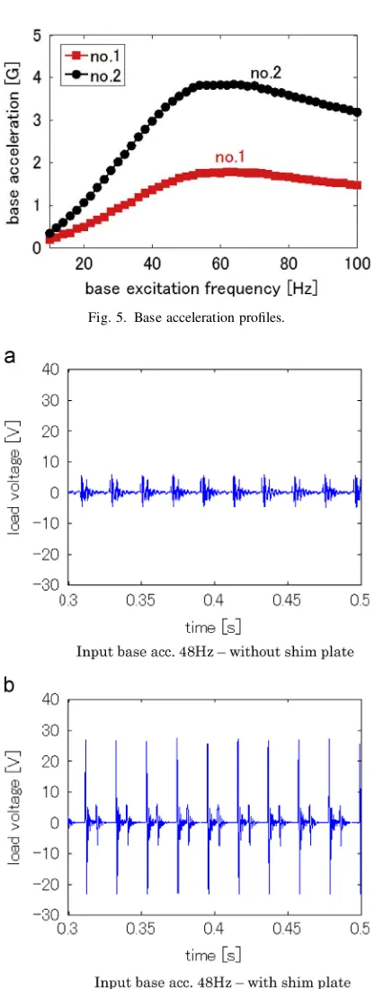
The profiles of the input base acceleration of the vibrator are shown in Fig. 5. The figure shows that changes in the frequency results in changes of the acceleration of the base. Both profiles reach their peak acceleration of approximately 3.7 G and 1.7 G, respectively, when the frequency is 60 Hz.
4.2. Experimental results and discussion
4.2.1. Time response
Fig. 6shows the time response of the power generator when the base excitation is 48 Hz for base excitation profile no.2 with a load resistor of 10 kΩconnected at the output.Fig. 6(a) shows the time response of the configuration without the shim plate, and Fig. 6(b) shows the response of the configuration with the shim plate on the piezoelectric device. It is obvious that the peak of the output voltage of the configuration with the shim plate is approximately 4.3 times higher than that of the configuration without the shim plate. Therefore, we can see the significance of the indirect impact configuration when compared to the confi g-uration of direct impact for the designated power generator. To analyze the effect of the impact configuration with the shim plate, the efficiency of the force transfer of both configurations needs to be studied.
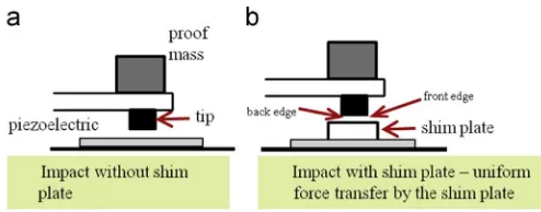
Fig. 7shows the structure of the impact area. In Fig. 7(a), the illustration of the impact without the shim plate is shown. As can be seen, it is difficult to ensure perfect contact of the impact of the tip on the piezoelectric device. The possibility of only some part of the tip coming in contact with the surface of the piezoelectric device is high. This kind of non-uniform impact reduces the efficiency of the force transfer from the tip to the piezoelectric device. In addition, a non-uniform strain force distribution develops by this impact configuration. If the power generator is in the non-touching configuration, the Fig. 5. Base acceleration profiles.
possibility that only the front edge of the tip will hit the device is high. The same thing could happen in the pre-load condition. This time, the only part of the tip that might hit the device is the back edge of the tip.
To optimize the contact of impact, a shim plate was placed on the piezoelectric device, as shown in Fig. 7(b). The advantage of this configuration is that, regardless of how the tip hits the shim plate, uniform contact of the impact can be expected. This also guarantees a relatively high efficiency of the force transfer through the shim plate. High efficiency of the force transfer and optimum contact of the impact reflect higher output power, as can be seen in the plot of the voltage drop inFig. 6(b).
4.2.2. Frequency response
The frequency responses of both the non-touching and pre-load configurations are compared inFig. 8. Thefigure shows the average output for 0.5 s when the diameter of shim plate was varied. The diameters of the shim plate were 4 mm, 6 mm, 8 mm and 10 mm, and the ratios of the diameters of the shim plate over those of the piezoelectric device were 0.16, 0.24, 0.32 and 0.4 m, respectively. The evaluation was conducted for a range of frequencies from 30 Hz to 100 Hz. For the plot of the non-touching configuration shown in Fig. 8(a), the average output power increased gradually from approximately 0.3 mW at the frequency of 30 Hz and up to 6 mW at the frequency of 74 Hz. The output power decreased abruptly after that frequency. This happened because at the frequency beyond 74 Hz, the tip was no longer able to reach and hit the piezoelectric device. In other words, at 74 Hz, the displacement of the tip was lower than 0.42 mm, which is the minimum distance needed to hit the device. From the same plot, at a frequency of about 62–64 Hz, a small drop of output power can be seen. It is clear that the drop is due to the structure anti-resonance that occurred at this frequency range. However, no significant different is seen in the magnitude in the plot for the different sizes of shim plate.
The frequency response of the pre-load configuration is shown in Fig. 8(b). In contrast with the output of the non-touching configuration, the operating frequency bandwidth of the power generator is wider for the pre-load configuration. The power generator is able to operate up to 100 Hz of the base excitation frequency. In terms of resonant frequency, the power generator reached its peak at two resonant frequencies: 76 Hz and 88 Hz. A clear difference in the magnitude of difference sizes of shim plates can be seen at the resonant
frequency of 88 Hz. The smallest shim plate produces the highest output, whereas the biggest shim plate produces the least output. This output is in line with the force analysis in Eq. (3). When their forces are the same, the smallest contact surface produces a higher indentation depth and subsequently produces a higher strain force. How small the contact surface should be for optimum output is another topic that should be analyzed in the future.
The power generator was tested with another set of input base accelerations. The frequency response of the pre-load configuration in Fig. 9 was obtained when base acceleration profile no. 1 was used as the input. As can be seen inFig. 5, the range of the base acceleration is lower than 2 G. In this plot, the frequency response of the configuration with a 4 mm and a 10 mm shim plate is shown. It is observed that the 4 mm shim plate is better than the 10 mm shim plate for producing higher output power.
5. Power generation from vibration of a moving vehicle
This section discusses the application of the designed power generator to generating electric power from a vehicle. The Fig. 7. Comparison of impact configuration.
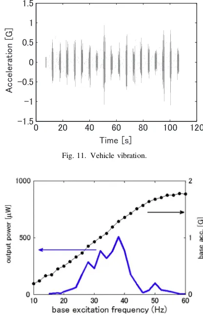
experimental apparatus shown in Fig. 10 was used to regenerate a real vibration of a moving vehicle. The apparatus consists of a PC, a digital to analog converter (DAC), an XZ-stage, and the power generator. The XZ-stage is a two-axis moving rail controlled by servo motors equipped with an acceleration control system[21]. The vertical axis is thez-axis and the horizontal axis is thex-axis. However, only thez-axis rail was used to regenerate the vibration. The power generator was installed at the z-axis rail so that, as the rail moves vertically, the tip of the power generator hits the piezoelectric device and produces electricity at the 10 kΩ load resistor connected to the output.Fig. 11shows the plot of vibration in the engine room of a moving truck. The size of the truck is 1.5 t. As shown in this figure, the vibration signal lasts for about 100 s.
As can be seen in thefigure, the acceleration of the vibration most of the time is less than 1 G. Therefore, to account for this condition, the specifications of the power generator structure used for this evaluation were changed in the following manner: the vibrating beam width was changed to 10 mm and the proof mass was changed to 26 g. The purpose of reducing the width of the vibrating beam was to reduce its spring constant. By changing these two variables, the operating frequency band-width of the power generator was expected to be reduced to the lower range. The frequency response of this power generator is shown inFig. 12. This frequency response was measured when
base acceleration profile no. 1 was used as the input. As seen in thefigure, the operating frequency bandwidth of the power generator, when compared to that of the previous confi gura-tion, is tremendously reduced to the lower range. The confi g-uration operates optimally at an input acceleration below 1 G. The voltage drop across the load resistor of the power generator is shown in Fig. 13. The density of the output voltage is relatively higher in the time range of 8 s to 107 s. The total energy output generated within this time is about 1.57 mJ. The generated energy seems to be low but, as the target of application of the designed power generator is to Fig. 9. Frequency response of pre-load configuration with input base
profile no.1.
Fig. 10. Experimental apparatus for vehicle vibration power generation.
Fig. 11. Vehicle vibration.
Fig. 12. Frequency response of the power generator in pre-load configuration.
power low power electronic devices such as LEDs and wireless sensor networks that are installed in vehicles, the energy generated from the power generator will be enough if few other optimization strategies are taken into consideration. The operation of for example wireless sensor nodes based on Zigbee-platform require energy in the range of 0.15 mJ/ 5 ms or 0.30 mJ/10 ms [22] for short packet of data transmission. This make the energy generated by the designed power generator is sufficient for such devices.
6. Conclusions
The design concept of a vibration-based impact mode piezoelectric ceramic power generator with increased effi -ciency has been discussed and analyzed. It was demonstrated experimentally that the designed power generator in a pre-load configuration is able to produce electrical output for a wider range of frequencies than that in the non-touching confi gura-tion. To optimize the output of each impact, it was shown that the efficiency of the force transfer and the contact of the impact needed to be considered and analyzed. As a result, the indirect impact configuration was found to be more efficient than the direct impact configuration in optimizing the output power. It was also demonstrated that application of the designated power generator to generating electric energy from vehicle vibration is also effective.
Acknowledgments
The corresponding author appreciates the Government of Malaysia and the Faculty of Electronics & Computer Engi-neering of UTeM for their financial support during his PHD study at Gunma University (KPT(BS)770524086441).
References
[1] S. Roundy, E.S. Leland, J. Baker, E. Carleton, E. Reilly, E. Lai, et al., Improving power output for vibration-based energy scavengers, IEEE Pervasive Comput. 4 (2005) 28–36.
[2] H.-B. Fang, J.-Q. Liu, Z.-Y. Xu, L. Dong, L. Wang, D. Chen, et al., Fabrication and performance of MEMS-based piezoelectric power gen-erator for vibration energy harvesting, Microelectron. J. 37 (2006) 1280–1284.
[3] W.-S. Jung, M.-J. Lee, M.-G. Kang, H.G. Moon, S.-J. Yoon, S.-H. Baek, et al., Powerful curved piezoelectric generator for wearable applications, Nano Energy 13 (2015) 174–181.
[4] H. Zhang, X.-S. Zhang, X. Cheng, Y. Liu, M. Han, X. Xue, et al., A flexible and implantable piezoelectric generator harvesting energy from the pulsation of ascending aorta: in vitro and in vivo studies, Nano Energy 12 (2015) 296–304.
[5]L. Deng, Z. Wen, X. Zhao, C. Yuan, G. Luo, J. Mo, High voltage output MEMS vibration energy harvester in d 31 mode with PZT thin film, J. Microelectromech. Syst. 23 (2014) 855–861.
[6]H. Hu, L. Hu, J. Yang, H. Wang, X. Chen, A piezoelectric spring mass system as a low-frequency energy harvester, IEEE Trans. Ultrason. Ferroelectr. Freq. Control 60 (2013) 846–850.
[7]M. Martinez, A. Artemev, A novel approach to a piezoelectric sensing element, J. Sens. 2010 (2010) 1–5.
[8]M.I. Friswell, S. Adhikari, Sensor shape design for piezoelectric cantilever beams to harvest vibration energy, J. Appl. Phys. 108 (2010) 1–7.
[9]A.A. Basari, S. Awaji, S. Wang, S. Hashimoto, S. Kumagai, K. Suto, et al., Shape effect of piezoelectric energy harvester on vibration power generation, J. Power Energy Eng. 2 (2014) 117–124.
[10]N. Kong, D.S. Ha, A. Erturk, D.J. Inman, Resistive impedance matching circuit for piezoelectric energy harvesting, J. Intell. Mater. Syst. Struct. 21 (2010) 1293–1302.
[11]H. Liu, C.J. Tay, C. Quan, T. Kobayashi, C. Lee, Piezoelectric MEMS energy harvester for low-frequency vibrations with wideband operation range and steadily increased output power, J. Microelectromech. Syst. 20 (2011) 1131–1142.
[12]M.A. Halim, J.Y. Park, Theoretical modeling and analysis of mechanical impact driven and frequency up-converted piezoelectric energy harvester for low-frequency and wide-bandwidth operation, Sens. Actuators A Phys. 208 (2014) 56–65.
[13]M. Song, Y. Zhang, M. Peng, J. Zhai, Low frequency wideband nano generators for energy harvesting from natural environment, Nano Energy 6 (2014) 66–72.
[14]H. Liu, C. Lee, T. Kobayashi, C.J. Tay, C. Quan, Investigation of a MEMS piezoelectric energy harvester system with a frequency-widened-bandwidth mechanism introduced by mechanical stoppers, Smart Mater. Struct. 21 (2012) 12.
[15]M.-C. Chure, L. Wu, K.-K. Wu, C.-C. Tung, J.-S. Lin, W.-C. Ma, Power generation characteristics of PZT piezoelectric ceramics using drop weight impact techniques: effect of dimensional size, Ceram. Int. 40 (2014) 341–345.
[16]E. Jacquelin, S. Adhikari, M.I. Friswell, A piezoelectric device for impact energy harvesting, Smart Mater. Struct. 20 (2011) 12.
[17]A.A. Basari, S. Awaji, S. Sakamoto, S. Hashimoto, B. Homma, K. Suto, et al., Study of the effect of mechanical impact parameters on an impact-mode piezoelectric ceramic power generator, Ceram. Int. 41 (2015) 12038–12044.
[18]W.D. Nix, H.J. Gao, Indentation size effects in crystalline materials: a law for strain gradient plasticity, J. Mech. Phys. Solids 46 (1998) 411–425.
[19]J.G. Swadener, E.P. George, G.M. Pharr, The correlation of the indentation size effect measured with indenters of various shapes, J. Mech. Phys. Solids 50 (2002) 681–694.
[20]A. Narimani, M.E. Golnaraghi, G.N. Jazar, Frequency response of a piecewise linear vibration isolator, J. Vib. Struct. 10 (2004) 20. [21]N. Nagai, S. Hashimoto, Y. Fujikura, J. Takahashi, S. Kumagai,
M. Kasai, et al., Reproduction of vehicle vibration by acceleration-based multi-axis control, Appl. Mech. Mater. 251 (2013) 129–133.