i
DESIGN AND DEVELOPMENT OF ANTENNA WITH FREQUENCY SELECTIVE SURFACES (FSS)
By
MUHAMMAD IMRAN BIN ROSLY
A thesis presented on application for the degree of
Bachelor of Electronic Engineering (Electronics Telecommunication) With Honours.
UNIVERSTI TEKNIKAL MALAYSIA MELAKA
FAKULTI KEJURUTERAAN ELEKTRONIK DAN KEJURUTERAAN KOMPUTER
BORANG PENGESAHAN STATUS LAPORAN PROJEK SARJANA MUDA II
mengaku membenarkan Laporan Projek Sarjana Muda ini disimpan di Perpustakaan dengan syarat-syarat kegunaan seperti berikut:
1. Laporan adalah hakmilik Universiti Teknikal Malaysia Melaka.
2. Perpustakaan dibenarkan membuat salinan untuk tujuan pengajian sahaja.
3. Perpustakaan dibenarkan membuat salinan laporan ini sebagai bahan pertukaran antara institusi pengajian tinggi.
4. Sila tandakan ( √ ) :
SULIT* *(Mengandungi maklumat yang berdarjah keselamatan atau
kepentingan Malaysia seperti yang termaktub di dalam AKTA RAHSIA RASMI 1972)
TERHAD** **(Mengandungi maklumat terhad yang telah ditentukan oleh
organisasi/badan di mana penyelidikan dijalankan)
TIDAK TERHAD
Disahkan oleh:
__ ________________________ ___________________________________
(TANDATANGAN PENULIS) (COP DAN TANDATANGAN PENYELIA)
“I hereby declare that the work in this project is my own except for summaries and quotations which have been duly acknowledge.”
iii “I acknowledge that I have read this report and in my opinion this report is sufficient
in term of scope and quality for the award of Bachelor of Electronic Engineering (Industrial Electronics/ Computer Engineering/ Electronic Telecommunication/
Wireless Communication)* with Honours.”
iii
DEDICATION
I dedicate this thesis to my beloved mother
Salmiah binti Othman
And
To the loving memory of my father
Rosly Bin Mohd Ghazalli
You have successfully made me the person I am now And
Acknowledgements
With the name of ALLAH S.W.T, The Most Gracious and Merciful. Praise to ALLAH S.W.T Almighty for giving me the will and wisdom to complete this entire project and also giving me opportunity to participate in performing this ‘Projek Sarjana Muda’ program, we would have some help and certain guidelines from any of the respected persons; someone whose deserve this greatest gratitude. The completion of this report has given me much pleasure and satisfaction. A salute to University Teknikal Malaysia Melaka (UTeM) for conducting this program for my course Bachelor of Engineering in Electronics (Telecommunication).
Hence, I can’t say enough thank you to Dr. Siti Normi Bt. Zabri@Suhaimi for giving me guidance and encouragement; with numerous advice and consultations in making the final project. The valuable knowledge and experience that was been shared from her are very much appreciated.
Special thanks also to my beloved mother, family members, classmates and team members; whose have made sort of brilliant ideas and comments on this final project report which has gave much inspiration to improve and improvise this report.
v
Abstract
The project report that produce by the student with their own initiatives and capabilities to ensure the chronology of the report is perfect and completed. This report contents of all research study to support the project from the start till the end of the Final Year Project (FYP).
Abstrak
Projek ini adalah hasil titik peluh pelajar dalam membuat persediaa dan kelengkapan dalam menyelesaikan projek ini; malah ia juga untuk memastikan kronologi laporan projek ini adalah lengkap dan dapan disempurnakan dengan jayanya. Ia terkandung beberapa bentuk pendapatan kajian untuk menyokong pelan projek daripada mula sehingga pengakhiran Projek Sarjana Muda (PSM).
vii 1.1 Introduction to Antennas ... 1
1.2 Microstrip Patch Antenna ... 1
1.3 Frequency Selective Surfaces (FSS) ... 5
1.4 Antenna with Frequency Selective Surfaces ... 7
1.5 Problem Statement ... 8
1.6 Objectives ... 8
1.7 Scope of Work ... 8
2 Literature Review Microstrip Patch Antenna Literature ... 10
2.1.1 Design, fabrication and characterization of microstrip square patch antenna array for X band applications ... 10
2.1.2 A Compact Microstrip antenna for X band Application ... 13
2.1.3 Design and Analysis of an X-band Phased Array Patch Antenna ... 15
2.1.4 Dual-band Microstrip Patch Antenna using Frequency Selective Surface for Satellite Communication Systems in S – Band ... 17
2.1.5 Rectangular Microstrip Patch Antenna with FSS and Slotted Patch to Enhance Bandwidth at 2.4 GHz for WLAN Applications ... 19
Frequency Selective Surfaces (FSS) Literature ... 22
2.2.1 Designing FSS for Wireless Propagation Control within Buildings... 22
2.2.2 Enhanced Gain UWB Slot Antenna with Multilayer Frequency-Selective Surface Reflector ... 24
2.2.3 Performance Improvement of a U-Slot Patch Antenna using a Dual-Band Frequency Selective Surface with Modified Jerusalem Cross Elements... 26
2.2.4 Design of a Dual-band Antenna using a Patch and Frequency Selective Surface for WLAN and WiMAX ... 28
2.2.5 Effect of FSS Structure on Planar Patch Antenna ... 29
2.2.6 Summary for Frequency Selective Surfaces ... 32
3 METHODOLOGY Projects Literature ... 33
Hardware (Model) ... 34
3.2.1 Rectangular Microstrip Patch Antenna ... 34
3.2.2 Frequency Selective Surfaces (FSS) Model ... 39
Software Simulation (CST Microwave Studio) ... 39
Project Flowchart ... 40
4 RESULT AND DISCUSSIONS Introduction ... 41
Microstrip Patch Antenna Design... 41
4.2.1 Analysis and Parameters of Antenna ... 42
4.2.2 Performance Comparison of the Designed Antennas ... 49
4.3 Frequency Selective Surfaces Analysis ... 50
4.3.1 Square – Circular Slotted ... 50
4.3.2 Hexagon – Slotted Hexagonal Loop ... 51
4.3.3 Square – Square Slotted ... 52
4.3.4 Performance Comparison of Frequency Selective Surfaces ... 53
4.3 Integrated Antenna with Frequency Selective Surfaces ... 54
ix 5 CONCLUSION AND FUTURE WORK
Conclusion ... 60
Future Work... 61
APPENDIX I: Antenna Author’s Comparison APPENDIX II: FSS Author’s Comparison APPENDIX III: RT Duroid Data Sheet
List of Figures
Figure 1.1: Various form of microstrip patch antenna ... 2
Figure 1.2: Microstrip patch antenna ... 4
Figure 1.3: Physical and effective length of a rectangular microstrip patch antenna .. 4
Figure 1.4: Rectangular microstrip patch antenna feedline ... 5
Figure 1.5: (a) Patch elements (b) Aperture elements... 6
Figure 1.6: The type of FSS elements ... 6
Figure 2.1: E – plane pattern of 4-element patch antenna ... 11
Figure 2.2: H – plane pattern of 4-element patch antenna ... 12
Figure 2.3: Frequency response of 4-element patch antenna ... 12
Figure 2.4: Radiation characteristics of 4-element patch antenna ... 12
Figure 2.5: Antenna 1 configuration ... 13
Figure 2.6: Antenna 2 configuration ... 13
Figure 2.7: Comparison between measured and simulate return losses for antenna 1 ... 14
Figure 2.8: Comparison between measured and simulate return losses for antenna 2 ... 14
Figure 2.2.9: Side view of the ACSP antenna with ground shield, via cage and RF-transition ... 15
xi Figure 2.11: Reflection coefficient at different angles (a) E-plane scan (ᵩ), (b) H-plane
scan (ᵩ) ... 17
Figure 2.12: Without FSS (a) Return Loss (b) VSWR ... 18
Figure 2.13: With FSS (a) Return Loss (b) VSWR ... 19
Figure 2.14: Fabricated microstrip patch antenna ... 20
Figure 2.15: Fabricated FSS ... 21
Figure 2.16: Super dense 2 layer linear dipole FSS ... 23
Figure 2.17: 3x3 element for 2 layer square loop FSS array ... 23
Figure 2.18: Measured and simulated transmission responses for inkjet printer and etched FSS. Solid line: measured, dot-dash line: simulated (inkjet), dashed line: simulated (etched) ... 24
Figure 2.19: Unit cell of second layer FSS with dual band behaviour ... 25
Figure 2.20: Theoretical gain over a frequency band ... 25
Figure 2.21: A U-slot patch antenna and its dimensions ... 26
Figure 2.22: A FSS with regular Jerusalem cross elements implanted in the U – slot patch antenna ... 27
Figure 2.23: Comparison of return losses for the smaller U-slot patch antenna with a modified FSS and the original U-slot patch antenna without using a FSS ... 27
Figure 2.24: antenna geometry (a) patch antenna and (b) FSS ... 28
Figure 2.25: Simulated gain of the proposed antenna ... 29
Figure 2.26: Dimensions of the antenna (in mm) ... 29
Figure 2.28: Comparative graph of Return Loss for FSS ... 30
Figure 2.29: Comparative graph of return loss with frequency of patch antenna with FSS at 21.1 mm ... 31
Figure 3.1: A rectangular patch model ... 34
Figure 3.2: Rectangular Feedline ... 36
Figure 3.3: Smith Chart ... 38
Figure 3.4: Project Flow Chart by sequence ... 40
Figure 4.1: Rectangular patch antenna parameters ... 42
Figure 4.2: Computed Return Loss for the antenna printed on a 1.5 mm substrate (Rogers RT 5880, ε = 2.2) ... 43
Figure 4.3: Z – smith parameter of the antenna printed on a 1.5 mm substrate (Rogers RT 5880, ε = 2.2) ... 43
Figure 4.4: Wave radiation pattern Rogers RT5880 (1.5 mm) ... 44
Figure 4.5: Rogers RT5880 (0.254 mm) Patch Antenna ... 44
Figure 4.6: Computed Return Loss for the antenna printed on a 0.254 mm substrate (Rogers RT 5880, ε = 2.2) ... 45
Figure 4.7: Wave Radiation Rogers RT5880 (0.254 mm) ... 45
Figure 4.8: Rogers RO3010 (1.28 mm) Patch Antenna ... 46
Figure 4.9: Computed Return Loss for the antenna printed on a 0.254 mm substrate (Rogers R03010, ε = 10.2) ... 47
Figure 4.10: Wave Radiation Rogers RO3010 (1.28 mm)... 47
xiii Figure 4.12: Computed Return Loss for the antenna printed on a 0.254 mm substrate
(Rogers R03010, ε = 10.2) ... 48
Figure 4.13: Wave Radiation Rogers RO3003 (1.52 mm)... 49
Figure 4.14: Square - Circular Slotted Unit Cell (a) front view (b) back view... 50
Figure 4.15: Computed Return Loss for the FSS of Square - Circular Slotted ... 51
Figure 4.16: Hexagon - Slotted Hexagonal Loop Unit Cell (a) Front view ... 52
Figure 4.17: Computed Return Loss for the FSS of Hexagon – Slotted Hexagonal Loop ... 52
Figure 4.18: Square – Square Slotted Unit Cell (a) Front view (b) back view ... 53
Figure 4.19: Computed Return Loss for the FSS of Square - Square Slotted Loop . 53 Figure 4.20: Integrated antenna and FSS frequency response ... 55
Figure 4.21: Integrated antenna Rogers 3010 and FSS frequency response ... 56
Figure 4.22: Antenna Rogers RO3010 real structures ... 57
Figure 4.23: Printed FSS (a) Front and (b) Side view ... 58
Figure 4.24: Antenna with FSS practical measurement ... 58
Figure 4.25: Microstrip patch antenna 10 mm distance with FSS ... 59
List of Table
Table 1.1: Types of antenna with descriptions... 2
Table 2.1: Antenna parameters ... 13
Table 2.2: Antenna array specifications ... 16
Table 2.3: Comparison of Simulated Results of Proposed Antenna ... 18
Table 2.4: Design parameters of microstrip antenna ... 20
Table 2.5: Comparison between simulated results microstrip patch and ... 21
Table 2.6: Comparison result of simulated and measured of antenna without FSS .. 31
Table 2.7: Planar patch antenna configuration ... 32
Table 4.1: Antenna Optimization ... 49
Table 4.2: Unit Cell Optimization ... 54
1
INTRODUCTION
1.1 Introduction to Antennas
This project describes on the “Design and Development of Antenna with Frequency Selective Surfaces”. The antenna is designed of a microstrip patch which
operates in the X band. Frequency Selective Surface (FSS) is placed at the hollow of the antenna structure to optimize the transmissivity wave from the antenna with low loss. It will be a specific Frequency Selective Surface (FSS) for their design as to sustain the bandwidth for this undertaking. The antenna transmits the wave at X band frequency as it passes through the FSS; with an optimized bandwidth and frequency range. It is very challenging to keep the antenna size small but at the same time producing a larger bandwidth because the larger the antenna the bigger the bandwidth. Hence, to ensure the antenna in miniature size; the analysis is required to meet the specifications of the antenna in terms of normal impedance, efficiency, directivity and gain.
1.2 Microstrip Patch Antenna
recipient and transmitter complex with electronic circuit connection to check the wave direction.
A microstrip antenna consists of an upper conductor on top of a dielectric substrate. Various conductor shapes have been proposed and investigated for the microstrip patch antenna. Common form of printed patch antennas are square, rectangular, circle, ring, triangle, and elliptical which are shown in Figure 1.1;
Figure 1.1: Various form of microstrip patch antenna
There are several types of antenna as shown in the table below;
Table 1.1: Types of antenna with descriptions
Antennas Profile Type and Descriptions
On the basis of radiation
Omni-directional antenna
- A weak directional antenna which radiate and receive in all directions.
Directional antenna
3
On the basis of aperture
Wire antenna
- Use everywhere such as buildings, ships, cars etc.
Aperture antenna
- Utilize in high frequencies; most useful in spacecraft and aircraft. Microstrip antenna
- Most use in space, government and commercial applications. Array antenna
- Gather several single antenna to maximize the radiation in particular direction.
On the basis of polarization
Linearly polarized antenna
- E – Field propagate either in vertical polarize antenna or horizontal vertical antenna.
Circularly polarized antenna
- E – Field propagate in any orientation.
The conventional design of a microstrip patch antenna consist of a conductor patch printed on a dielectric substrate that is mounted together. Yet this character of a conventional antenna has its flaw which is narrow bandwidth. Figure 1.2 shows the physical structure of a microstrip patch antenna.
Figure 1.2: Microstrip patch antenna
This type of antenna radiate on the main plane because of the fringing fields that exist between the patch edge and the ground plane. The design can be explained based on the Transmission Line model.
Figure 1.3: Physical and effective length of a rectangular microstrip patch antenna
Figure 1.3demonstrates the effective duration of a patch antenna radiation with the substrate material. The relationship between size and the dielectric constant of the dielectric substance is the element that will affect the frequency band of the microstrip patch antenna.
There are various methods of feeding in the design of a microstrip antenna:
Microstrip Line.
Coaxial Probe (coplanar feed).
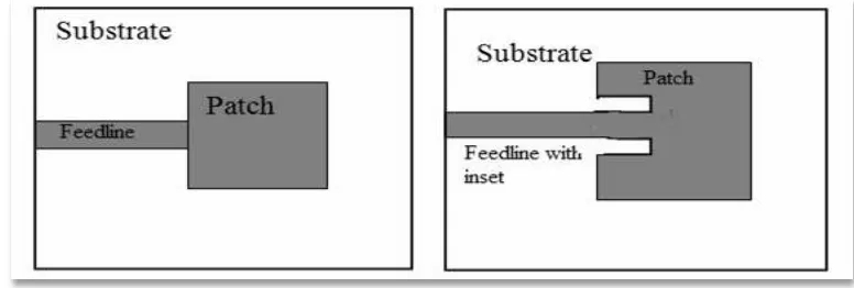
5 The most significant matter to be debated is the maximum power transfer i.e (matching of the feed line with the input impedance of the antenna), which discussed in section. There are certain designs which have been put aside because of their poor feeding. Designer can construct an antenna with good features and good radiation parameter and high efficiency, but when the feeding is bad, the total efficiency could reduce to a low level which causes the whole system to be not optimize. An example of a feedline that is used in this project is shown in Figure 1.4;
Figure 1.4: Rectangular microstrip patch antenna feedline
1.3 Frequency Selective Surfaces (FSS)
(a) (b) Figure 1.5: (a) Patch elements (b) Aperture elements
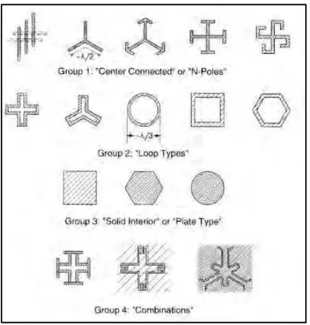
There are four major types of FSS, which can be seen in Figure 1.6. The first
group includes the center connected elements for example simple straight element, three legged element, anchor element, Jerusalem cross and square spiral.
Meanwhile, the loop types are categorized in group 2 for example three and four-legged loaded element, circular loops, square and hexagonal loops. Group 3 include patch type of combinations.
Figure 1.6: The type of FSS elements
7 surface is curved rather than categorical. A novel design of a three dimensional frequency selective surface is interesting and challenging.
The advantage of the 3D structure is its excellent space utilization. In theory, the resonant frequency is limited by the resonant length in a unit cell. The previous techniques researched on miniaturized FSS are essential to elongate the resonant length in two-dimensional. With the utilization of three-dimensional space, the unit cell size of the FSS can be further diluted. On the other hand, an FSS with a stable frequency response to different types of polarization of different oblique angles is needed.
1.4 Antenna with Frequency Selective Surfaces
FSS's can be utilized to determine the frequency and the angle response of an antenna. It depends on the shape of the FSS and the bandwidth of the transmitting aerial. On that point is more flexibility in choosing the element of the FSS to be fitted with the designated antenna besides from using the formal method.
From the image above, the wave beam direction will have an impingement on the FSS surfaces. The FSS plane cover all the wave radiated with proposed of low losses during the transmission. The main role of the FSS is either to be a filter or a reflector. If the antenna act as a filter, it will assist to optimize the wave while a reflector FSS will not allow frequency at specific bandwidths designated for the FSS to pass through the planer.
1.5 Problem Statement
Grounded along the data, there are many types of antenna with FSS design. All of the designs shown different result of bandwidth range and wave optimization. It was known that the bigger the size of the antenna the bigger it will be for the bandwidth. Logically, it will not apply to have a bigger antenna at particular location, such as rooftop; it will waste space and energy consumption for the antenna.
1.6 Objectives
This research provides a comprehensive analysis for the carrying out optimization of both microstrip antenna and frequency selective surface.
The central aims of this research work are as follows:
To understand the relationship between antenna application and FSS. To design an antenna and FSS for the selected frequency band.
To simulate the bandwidth enhancement of the selected antenna within the frequency range.
1.7 Scope of Work
This specific design of the microstrip patch antenna with FSS regarding with the antenna efficiency and bandwidth optimization. Therefore, the antenna reduces the return loss and enhances the bandwidth and gain in X band at the resonance of 8 GHz to 12 GHz; which in part of the X band range of frequency.