‘Saya/Kami* akui bahawa telah membaca karya ini dan pada pandangan saya/kami* karya ini
adalah memadai dari segi skop dan kualiti untuk tujuan penganugerahan Ijazah Sarjana Muda Kejuruteraan Mekanikal (Termal Bendalir)’
Tandatangan : ……… Nama Penyelia : ... Tarikh : ...
SAIFUDDIN BIN NGSPAR
This dissertation is submitted as partial fulfillment of the requirement for the degree of Bachelor of Mechanical Engineering (Thermal Fluid)
Faculty of Mechanical Engineering Universiti Teknikal Malaysia Melaka
“I declare that this report is done by my own exclude citation with the mentioned references foe each.”
Signature : ………
Author : ……….
ABSTRAK
iii
ABSTRACT
CONTENT
CHAPTER TITLE PAGE NUMBER
ACKNOWLEDGMENT i
ABSTRAK ii
ABSTRACT iii
CONTENT iv
LIST OF TABLE vii
LIST OF FIGURE viii
LIST OF SYMBOL x
LIST OF APPENDIX xi
CHAPTER 1 INTRODUCTION 1
1.1 Background 1
1.2 Project title 2
1.3 Objective of the research 2
1.4 Problem statement 2
1.5 Scope of project 3
v
CHAPTER TITLE PAGE NUMBER
CHAPTER 3 THEORY 12
3.1 Introduction 12
3.2 Wave classification 13
3.2.1 Airy Wave theory: sinusoidal waves 13 3.2.2 Stokes Wave theory: trochoidal 13
3.2.3 Solitary wave theory 13
3.3 Wave theory 14
3.4 Wave mechanics 14
3.5 Wave parameters 17
3.6 Shoreline device 19
3.6.1 Oscillating Water Column device 19
3.6.2 TAPCHAN device 20
3.6.3 The pendulor device 21
3.7 Wave tank 21
3.8 Calculation theory 22
3.9 Buoyancy 24
3.10 Working theory 25
CHAPTER 4 METHODOLOGY 26
4.1 Introduction 26
4.2 Measuring the wave force 26
4.3 Measuring the wave height 27
4.4Fabrication process 28
4.4.1 Wave tank 28
4.4.2 Wave energy machine 30
4.4.2.1 The paddle and center bearing 29
4.5 Final test 32
4.6 Flow chart 33
4.4.3 PSM 1 33
CHAPTER TITLE PAGE NUMBER
CHAPTER 5 FABRICATION PROCESS 35
5.1 Introduction 33
5.2 The wave tank (testing device) 35
5.2.1 List of material 36
5.2.2 Apparatus 36
5.2.3 Procedure 37
5.3 Wave energy machine 38
5.3.1 List of material 38
5.3.2 Apparatus 39
5.4 Buoy casing. 40
5.4.1 Procedure 41
5.5 Arm (aluminum rod arm) 41
5.5.1 Procedure 41
5.6 Paddle 43
CHAPTER 6 RESULT 44
6.1 Wave energy machine 44
6.1.1 Paddle distance test 44
6.1.2 Water depth test 46
6.1.3 Voltage output test 47
CHAPTER 7 DISCUSSION 49
CHAPTER 8 CONCLUSION 51
REFERENCES 52
vii
LIST OF TABLE
NO. TITLE PAGE NUMBER
5.2.1 List of material 36
5.3.1 List of material 38
6.1.1 Paddle distance test 46
6.1.2 Water depth test 46
LIST OF FIGURE
NO. TITLE PAGE NUMBER
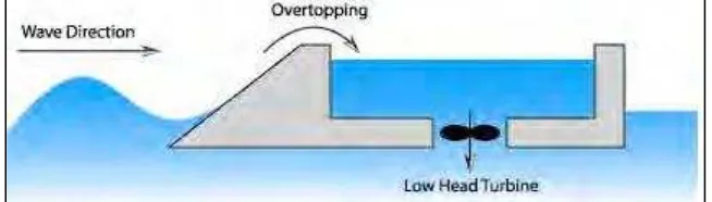
2.1 Overtopping Devices 5
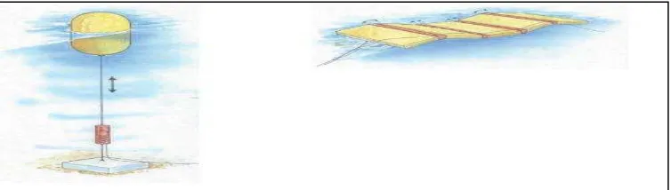
2.2 Taut moored device and hinged contour device 6
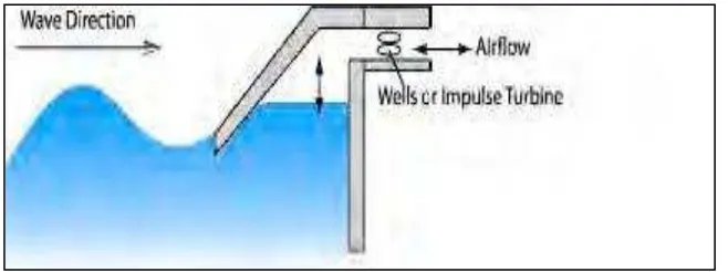
2.3 Oscillating Water Column (OWC) 7
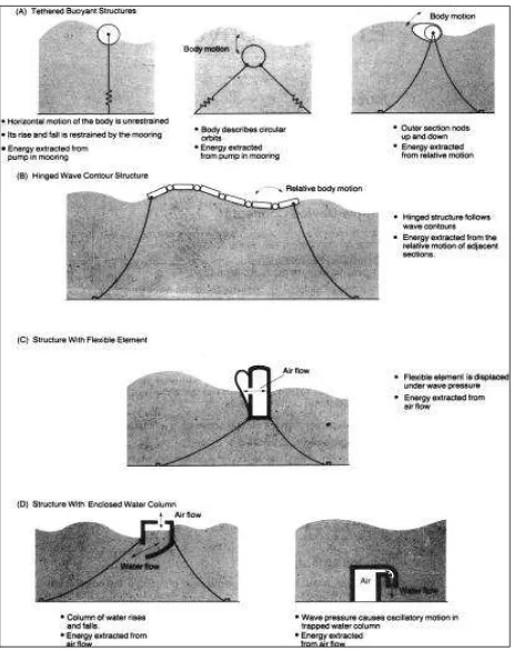
2.4 Tethered buoyant structure 10
3.2 Wave classification 14
3.4. Definition sketch of free surface wave parameters 16
for a linear progressive wave and the fluid
particle velocities and accelerations associated
with each portion of the wave.
3.5 Fluid particle paths for linear progressive waves in 18
different relative water depths.
3.6.1 Oscillating Water Column device. 19
3.6.2 TAPCHAN device. 20
3.7 Wave Tank 22
4.2 Jig to measure the wave force 26
4.3 Jig to measure the wave height 27
4.4.1 (a) Fabricated Wave Tank 28
4.4.1 (b) Wave Tank design 29
4.4.2 Wave energy machine 30
ix
NO. TITLE PAGE NUMBER
4.6.1 Flow chart of PSM 1 33
4.6.2 Flow chart of PSM 2 34
5.2.3 Five plates 37
5.4 (a) Buoy casing dimension 40
5.4 (b) Fabricated buoy casing 40
5.5.1(a) Arm design 42
5.5.1(b) Fabricated arm 42
5.6 Paddle 43
6.1.1 Paddle distance test 45
LIST OF SYMBOL
L = wave length (m)
T = period
d = depth (m)
k = wave number
H = Wave height
E = wave energy
t = time
F = Frequency (1/T)
C = celerity (L/T)
H/2 = amplitude P.E = Potential energy
m = mass
ρ = water density W = wave width (m) k = wave number (2π/λ) λ = wave length (gT2/2π) ω = wave frequency (rad/sec) K.E = kinetic energy
EWD = Energy density
Pw = Power
PWD = Power density
xi
LIST OF APPENDIX
NO TITLE PAGE NUMBER
A Hydropower 54
B Wave Energy Conversion Technology 55
C Buoyant Moored Devices 57
D Oscillating Water Column Principal 58
E Calculation of Wave 59
CHAPTER 1
INTRODUCTION
1.1 Background
Oceans cover almost three-fourths of the earth‟s surface. The oceans and the land
beneath them could provide all of the energy the world needs for years to come. The oceans contain a huge energy resource that can be exploited to feed the global energy demand. The most developed conversion systems concern: tidal energy, which results from the gravitational fields of the moon and the sun; thermal energy (Ocean Thermal Energy Conversion or OTEC), resulting directly from solar radiation; marine currents, caused by thermal and salinity differences in addition to tidal effects and ocean waves, generated by the action of the winds blowing over the ocean surface.
The power present in ocean waves has been recognized for centuries although mostly in terms of its destructive potential. However, the possibility of obtaining useful energy from ocean waves has been considered for some centuries. The first patent of a wave energy device was registered in France by the Girards father and son at the end of 18th century and since then more than one thousand patents have been filed in various
countries.
2 shore as well as off shore. Off shore systems use the motion of the waves either to create an electrical charge, or to operate hydraulic pumps. The pressurized fluid from the pumps powers a turbine. There are several technique that been using for onshore systems which are the pendulor, the tapchan and the oscillating water column.
This project is focusing on designing and assembling the wave energy converter device that manipulate the wave energy and transfer it to electrical energy. Several experiments and tests will be prepared in order to achieve the main idea.
1.2 Project title
The study of the Wave Energy Machine
A devise that been used to convert wave energy to electrical energy. The device will be used onshore to get the wave energy. The energy conversion in this project:-
[wave energy mechanical energy electrical energy]
1.3 Objective of the research
To develop and assemble wave energy converter that will be use onshore. In order to develop this device, onshore wave characteristic must be known. To study the design and fabricate wave energy machine
1.4 Problem statement
Every single design of wave energy converter that exist nowadays is made to supply high energy power that been used for heavy industrial. There is no design for generating small range of power to be use onshore.
1.5 Scope of project
4
CHAPTER 2
LITERATURE REVIEW
temporarily deployed in the sea. These devices needs to be at or near the water surface and requires flexible moorings and underwater electrical transmission cables in order to extract energy from the waves (Pontes and Falcão,2008).
[image:18.612.164.491.251.344.2]
According to Kane (2008), Overtopping Devices uses a ramp, up which waves can run and overtop into a basin located behind it. The basin then empties back into the ocean, driving a low-head turbine. The device can be either shore-based or floating.
6 Buoyant Moored Device floats on or below the water surface and converts the orbital motion of surface waves into electricity using an absorber system. Two different types of Buoyant Moored Device which are Taut moored device that extracts energy from the relative motion between buoy and sea floor and hinged contour device which the energy of oscillating waves is captured by the movement of hinges that link adjacent floating panels.
[image:19.612.140.517.231.338.2]Kane (2008), also mention about the Oscillating Water Column (OWC) that use an enclosed column of water as a piston to pump air. These structures that can float, be fixed to the seabed, or be mounted on the shoreline uses an air turbine to convert air flow into a high frequency rotational output required by the turbine machinery.
Figure 2.3 Oscillating Water Column (OWC)
Kane (2008), added that shoreline devices have lower maintenance and installation costs than offshore devices and do not require moorings and long underwater electrical cables. Near shore devices are structures situated in shallow waters (typically 10 to 25 m water depth) and the OWC is the main type of device, with several designs install worldwide. Offshore devices are situated in water depths of more than 40m which is more energetic wave resource, lower environmental impacts and larger wave resource.
8 sausages. The pressurized fluid from the pumps powers a turbine. Onshore techniques include the pendulor, the tapchan and the oscillating water column. The pendulor uses a flap swung back and forth by waves to power a pump and generator. The tapchan is a tapered channel that forces waves higher and thus feeds water into a reservoir above sea level and then used to turn a turbine. Tidal Energy requires a large volume of fast-moving water that can be found either in location with a wide swing in tidal heights or with tidal flows that pass through a narrow channel. There are three types of ocean thermal energy conversion (OTEC) that been discuss which are closed-cycle, open-cycle and hybrid method. Closed-cycle uses warm seawater to vaporize a low-boiling point liquid that then drives a turbine to generate electricity. The vaporized liquid then is cooled and condensed back to liquid with cold seawater, and the cycle repeats. Open-cycle uses warm seawater to boil through lowered pressure and uses the resulting steam to drive the turbine. Cold water from the deep converts the steam back to (now desalinated) water. Hybrid method uses the steam from boiled seawater to vaporize a low-boiling point liquid, which then drives the turbine (internet source, 20 August 2008).
10