DOI: 10.12928/TELKOMNIKA.v14i2A.4351 101
Software Running Dynamic Reconfiguration Model
Based on B Diagram
Wang Ying*1, Mickey Howard2 1
Department of Electronic Information and Electrical Engineering, Leshan Vocational & Technical College, Leshan, Sichuan, 614000, China
2
Computer Department, Marathon Oil Company, Berkeley, USA *Corresponding author, e-mail: [email protected]
Abstract
Aiming at limited support of formalization method of present software system structure for dynamic nature, adaptability nature of system structure and that it cannot verify dynamic characteristics of consistency, integrity in the evolution process of the system, put forward dynamic reconstruction system based on B Diagram theory integrating π calculation and Mobile Ambient calculation during operation of software; emphasize two factors of calculative position and connection; establish relatively completed and extensible theoretical structure. Therefore, B Diagram not only meets the requirement of self-adaption software to structure and interaction, but also provides intuitive and universal presentation ability. Briefly introduce basic conception and current situation; provide formalization rules to self-adaption system structure by B Diagram theory. Analyze and verify nature of dynamic evolution of system; investigate advantages and research direction of self-adaption system structure in formalization aspect.
Keywords: B Diagram; Self-adaption software; Software system structure; Dynamic reconstruction
1. Introduction
Based on traditional technology of software system structure, structure of self-adaption software system pays more attention to changes in system structure and behavior. At the same time, structure of self-adaption software system pays attention to the relationship of environment, structure and behavior; in addition, ensure validity of system in evolution process. Formalization method can provide accurate representing method and engineering rule guidance for structure of self-adaption software system and can analyze and deduce evolution of the system, which is helpful for auxiliary tools for self-adaption software system. At present, formalization methods of structure of self-adaption software system can be divided into two kinds: descriptive language (ADL) and universal formalization method, ADL including Wright Darwin, -ADL, etc.; universal formalization method includes CHAM, figure, etc. Although these methods have made some achievements and can verify some natures in system structure, they can not verify dynamic nature of uniformity and completeness in evolution process of system structure although these methods stress dynamic nature of system structure [1].
2. B Diagram Model of Structure of Self-Adaption Software System
Combined with our research work, this section investigates formalization aspect of structure of self-adaption software system by B Diagram theory and present research achievement. Literature [2] points out that formalization of dynamic system structure shall include structure, behavior and change. Therefore, formalization methods of structure of self-adaption software system shall include environment, structure, behavior, change and relationship of the three aspects. Therefore, external environment and system structure itself shall be described by B Diagram, of which system structure includes two aspects of structure and behavior.
2.1. Aspect of Structure
includes vocabulary table and a group of restriction. Vocabulary table includes some components, linkers and types of their interaction points. Restriction shows how system combines components and linkers. We describe system structure and style by concepts of BRS type, as is shown in Table 1. It can be seen that system structure and B Diagram can match well in concepts level.
Table 1. Mapping relationship of system structure and concepts of BRS type Self-adaption system structure Extensive BRS type
Structure
Component
Extensive B Diagram
Panel point
Linker Panel point
Configuration side Port Port Role Port Internal Representation Location
Mapping relationship Side Component type
Extensive control
Control
Type of linker Control
Type of port Type
Type of role Type
Restriction Restriction condition of type Operation of system structure Extensive operation of B Diagram
Reassortment Reaction rule
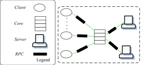
Next, it can be explained by style of system structure of three-level Client-Server. Considering service system of network information, users can send out service request to distributional servers by Core. In dynamic network environment, the number of clients and servers is varying continuously. For example, users can join in or leave. Servers can be disconnected with Core without service request. Therefore, such system structure can adjust by self-adaption according to request numbers of users. Figure 1 lists and shows specific operation status of this type of system structure.
Figure 1. B diagram description of living case of three-level client-server style
Client{port request},Server{port reply},RPC{role caller, callee},Core{port in out , } Components and linkers of this case include: Client{port request},Server{port reply},RPC{role caller, callee},Core{port in out , }.
We take specific system structure as a B Diagram. Change operation of system structure includes: add, cancel, replace components or linkers, ports Configuration and role connection, etc. We can realize the following system structure operation by modifying B Diagram. Therein, A represents system structure; U and V are items in A; P represents components or linkers; p represents ports; r is role.
Add(P, U(V), A)= // add P into U Remove(P, A)= // cancel P in A
Replace(P, P, A) = // replace P in A with P Connect(p, r, A)= // connect p and r Disconnect(p, r, A) = // disconnect p and r Rely(t, t’, A)= // mapping t and t’
Disrely(t, t’, A) = // disconnect mappingof t and t’
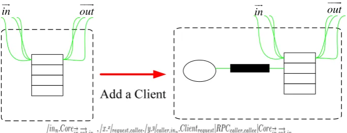
In addition, we can show structure change by making use of reaction rule in BRS. Therefore, effect of system structure operation can be shown intuitively. For example, we add a Client by reaction rule in Figure 2.
in
out
in out
Figure 2. Reaction rule of adding a client
2.2. Aspect of Behavior
In behavior aspect of system structure, present formalization methods almost make use of theories of calculation and figure theory, etc. One objective of B Diagram is to provide universal frame for movement and concurrence theories. Therefore, these formalization methods can be described by B Diagram, namely, transform these behaviors rules into B Diagram model. Next, we transform grammar of calculation into binding B Diagram.
behavior ::=prefix.behavior
| if boolean then {behavior1} [else {behavior2}] | choose {behavior1 or behavior2 or …behaviorn} | variant assignment
| replicate behavior | inaction
prefix::=via face send value | via face receive value
Semantic interpretation, therein, if, then, else, choose, inaction, replicate, send, get are inactive control.
[if boolean then {behavior1} else {behavior2}] = if boolean (then ([behavior1]) | else ([behavior2]))
1 2
[behavior ] if boolean=true
[behavior ] if boolean=false
[choose {behavior1 or behavior2 or …behaviorn}] = choose ([behavior1] | …| [behaviorn])
= [behaviori] i{1, 2…, n} [inaction]=inaction
[replicate behavior]=replicate [behavior] =[behavior] | replicate [behavior] [viansendv]=sendnv
As for change of component and connection, we can bind join quit activate and deactivate operation to express [3-6] by dynamic binding. Therefore, components and linkers can join in or exit some behavior rules dynamically and place behavior in active or inactive status, in order to show different behaviors in varying environment.
Figure 3. Dynamic binding mechanism
For example, if we add Authentication component in Core, therefore, initial behavior rule of Core is Ordinarybehavior; certification behavior rule is Safetybehavior; specific description is as following [7-10]:
Ordinarybehavior = via in receive n; inaction; via out send n;
Safetybehavior = via in receive n; if authentication (n) then {via out send n} else {via in send FAILURE};
However, behavior change can be explained by dynamic binding operation, namely, quit(Ordinarybehavior); join(Safetybehavior);
2.3. Environmental Aspects
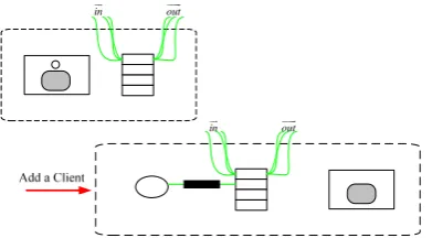
As is introduced in Section 2.2, B Diagram possesses universal expressive ability. Therefore, users can give definition to environment by their own way. For example, panel point in B Diagram can represent location, entity and events, etc.; side can represent connection, relationship and triggering condition, etc. We can introduce environment information for this example: represent Client number (correspond to numbers of internal circles) that can be accepted by present system by making use of Container. Reaction rule of adding a Client can be shown as Figure 4 [11-14].
in
out
in out
As for self-adaption software, change of environment will have influence for system structure, so that it will lead to changes of structure and behavior. Change relationship of environment, structure and behavior can be shown as:
//changes of structure and behavior caused by environment EnvChange(StructuralChange | BehavioralChange)+
// changes of structure, of which op is system structure operation StructuralChange::=op+ | reaction rule
//behavior change, which uses dynamic binding operation
BehaviralChange::=(join(h) | quit(h) | activate(h) | deactivate(h) )+
3. Verification of Nature
When carrying out these changes in operation period, ensure that these changes will not destroy system structure and uniformity, completeness of behavior. It is necessary condition for whether self-adaption evolution can be carried out.
3.1. Uniformity
Definition 2: as for behavior expression BE1 and BE2, so call behavior BE2, simulating behavior BE1 (briefly called as ), if the following condition meets one of the conditions:
1. BE1 = BE2
2. As for reaction rule , if , so there is , to make and
. From Definition 3, we can deduce that means that behavior ability of BE2 is either the same with or stronger than BE1. BE2 can also be regarded as refinement of BE1.
Definition 3: as for behavior expression BE1 and BE2, if there is a sequence tr composed by reaction rule, which makes , so BE1 is compatible with BE2. (Briefly record as ).
Definition 4: as for port p and role r, their behavior expressions are BEp and BEr; if they conform to , p and r are compatible (Briefly record as ) .
This definition shows that their behaviors must be compatible, namely, they can complete interaction and similar deadlock condition will not occur.
Definition 5: as for port p1 and p2, expressions of their behavior respectively are and . If they conform to , we regard p2 as refinement of p1. (Briefly record
as ).
In order to make all elements of new system structure still keep the same, we restrict evolution process and make system structure evolved based on ensuring uniformity. System is evolved according to certain operation. These operations include addition, cancellation or renewal of system structure elements. These operations constitute complex evolution. If every operation keeps uniformity of system structure, the whole evolution process keeps uniformity.
Definition 6: components (Comp) are uniform and they must meet the following conditions:
1. As for any configuration connections (p, r) in Comp, they shall meets ; 2. As for any mapping in Comp, they shall meet ;
3. Any subcomponent in Comp is uniform. 4. Any sub-linker in Comp is uniform.
Similarly, uniformity of linkers is shown as Definition 6. What’s more, we can regard the whole system structure as a composite component. By using these basic operations, we can modify structure and behavior of the whole system structure, but at the same time, system uniformity shall be ensured. Therefore, we explain evolution of system structure from three aspects of precondition, structure and behavior. Herein, we suppose that all components and linkers are consistent. For example:
Add (P, A)
Replace(P, P)
Connect(p, r)
Disconnect(p, r)
Rely(t, t’)
Disrely(t, t’)
Theorem 1: assuming that system structureArch is uniform, Arch is still uniform after basic operation of system structure.
Proof: Theorem 1 can be deduced from Definition 4, 5 and 6 according to four conditions of uniformity.
3.2. Completeness
Completeness means evolution of system cannot destroy restriction condition in system structure rules. Completeness also means that states of system before or after evolution will not be lost, or system will become “unsafe” and even cannot operate properly. Because evolution is determined by operation system according to self-adaption rule, completeness needs to be verified.
For example, as for three-level Client-Server style, the number of client-side and server are not limited, but there must have a Core. Therefore, this restriction condition of three-level Client-Server style can be expressed as A=◇Core by BiLog. What’s more, add Authentication components in order to provide safe system for users, but it needs to be ensured that Authentication needs to be embedded into Core. This restriction condition can be expressed as A=Authentication◦Core by BiLog.
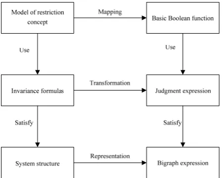
As for judgment for completeness, we aim at B Diagram of system structure to check one by one. Specific process is shown in Figure 8. Core of this method is to map above-said restriction concept into basic Boolean function; transform invariance formulas constituted by concept model into judgment expression; finally, check every invariance formula of system structure by corresponding detection function one by one. Only legal modification can be used in model of system structure. Modification that destroys restriction will be reported for errors or prevented. For example, as for BiLog formula ◇Core, we can check it by B Diagram expression and judge whether system has Core panel point after evolution. As for formula AuthenticationCore, it can be checked by judging whether Core is father panel point of Authentication.
4. Conclusion
B Diagram theory can lay solid basis for formalization method for system structure of self-adaption software, but there are still some problems to be solved: directive method for contextual information: present system increasingly requires continually operation and needs to respond to ever-changing resource and inner status, which needs to add contextual information to describe condition that leads to this change. Therefore, researches shall be made on how to conduct stipulations of agreement for contextual information and which method shall adopted to direct such stipulations of agreement; description language for system structure of self-adaption: present ADL lacks description to environment and its theoretical basis is not sufficient to verify evolution nature of self-adaption software.
References
[1] Bao G, Liang M, Geng Y, et al. A video-based speed estimation technique for localizing the wireless capsule endoscope inside gastrointestinal tract. EMBC. 2014; 5615-5618.
[2] Dadkhah M, Obeidat MM, Jazi MD, Sutikno T, Riyadi MA. How can we identify hijacked journals?
Bulletin of Electrical Engineering and Informatics. 2015; 4(2): 83-87.
[3] Jiang D, Ying X, Han Y. Collaborative multi-hop routing in cognitive wireless networks. Wireless Personal Communications. 2015; 1-23.
[4] Jinyu Hu and Zhiwei Gao. Modules identification in gene positive networks of hepatocellular carcinoma using Pearson agglomerative method and Pearson cohesion coupling modularity. Journal of Applied Mathematics. 2012.
[5] Jiang D, Xu Z, Chen Z. Joint time-frequency sparse estimation of large-scale network traffic.
Computer Networks. 2011; 55(15): 3533-3547.
[6] Jinyu Hu, Zhiwei Gao, Weisen Pan. Multiangle Social Network Recommendation Algorithms and Similarity Network Evaluation. Journal of Applied Mathematics. 2013.
[7] Valenzuela JE, Espinosa JMC, Torres AS, et al. Diagnosis of follicular lymphoma of the small intestine using videocapsule endoscopy. Revista Espanola De Enfermedades Digestivas Organo Oficial De La Sociedad Espanola De Patologia Digestiva. 2014; 106(1): 51-52.
[8] Oluwole FJ, Olajide OY. Radio frequency propagation mechanisms and empirical models for hilly areas. International Journal of Electrical and Computer Engineering (IJECE). 2013; 3(3): 372-376. [9] Gan Yan, Yuxiang Lv, Qiyin Wang, Yishuang Geng. Routing algorithm based on delay rate in
wireless cognitive radio network. Journal of Networks. 2014; 9(4): 948-955.
[10] Lin Y, Yang J, Lv Z. A Self-Assessment Stereo Capture Model Applicable to the Internet of Things.
Sensors. 2015; 15(8): 20925-20944.
[11] Zhang L, He B, Sun J. Double Image Multi-Encryption Algorithm Based on Fractional Chaotic Time Series. Journal of Computational and Theoretical Nanoscience. 2015; 12: 1-7.
[12] Arora VK. Quantum Nanoengineering Nonequilibrium High-Electric-Field Transport for Signal Propagation. Proceeding of the Electrical Engineering Computer Science and Informatics. 2015; 2(1): 1-9.
[13] T Sutikno, AZ Jidin, A Jidin, NRN Idris. Simplified VHDL coding of modified non-restoring square root calculator. International Journal of Reconfigurable and Embedded Systems. 2012; 1(1): 37-42. [14] Lv Z, Halawani A, Feng S. Multimodal hand and foot gesture interaction for handheld devices. ACM