UNIVERSITI TEKNIKAL MALAYSIA MELAKA
STUDY AND MEASUREMENT OF CUTTING TOOL COATING
THICKNESS BY USING BETA THICKNESS GAUGING METHOD
This report submitted in accordance with requirement of the Universiti Teknikal
Malaysia Melaka (UTeM) for the Bachelor Degree of Manufacturing Engineering (Manufacturing Process) with Honours
By
MOHD HILAL BIN ABDUL AZIZ (B050710248)
Supervisor:
MR. MOHD FAIRUZ BIN DIMIN
ABSTRACT
There are many types of methods in measuring the coating thickness. One of the methods is by using Beta Thickness Gauging method. The purpose of this study is to
ABSTRAK
Terdapat pelbagai jenis kaedah yang digunakan dalam mengukur ketebalan lapisan saduran. Salah satu daripadanya ialah dengan menggunakan kaedah pengukur ketebalan
beta (β). Tujuan eksperimen dan pembelajaran ini adalah untuk menentukan ketebalan
lapisan saduran pada mata alat dengan menggunakan teknik pengukuran sebar-balik beta
DEDICATION
ACKNOWLEDGEMENT
Firstly, I would like to acknowledge and express my gratitude and appreciation to my supervisor, En. Mohd Fairuz Bin Dimin for his supervision, encouragement, suggestion, advice and support. An appreciation too for my parents Abdul Aziz Bin Mohd Nasir and Nor Aziyah Binti Mohd Shohor whose give a constant encouragement, faith, confidence, and continuously of moral support.
It is a pleasure for me to express huge gratitude to all individuals and colleagues which have contribute so much throughout my study and give commitment during this research. Not forget to my friends and other people that are not listed in fulfilling this research, whereas their advice and assistance in various ways was extremely helpful. I could offer here only an inadequate gesture of my appreciation and all of your good deeds will always be in my mind.
TABLES OF CONTENTS
2.3 Backscattering Technique Experimentally ... 16
2.4 Titanium Aluminium Nitride Usage ... 24
CHAPTER 3 : METHODOLOGY ……….….…... 31
3.1 Introduction ... 31
3.2 The Procedures in the Effective Design of Experiment (DOE) ... 33
3.3 Materials Selection ... 37
3.3.2 Titanium Aluminium Nitride ... 39
4.2 Result of Measurement for Strontium-90 and Cobalt-60 Sources ... 52
4.3 The SEM Images of Cutting Tool Samples ... 55
CHAPTER 5 : DISCUSSION ………... 59
5.1 Introduction ... 59
5.2 Coating Thickness Measurement by Using Beta Sources and Backscatter Technique ………... 60
5.3 Comparison Result between GM Counts and SEM Coating Thicknesses ... 61
5.4 Possible Factors in Affecting the Measurement Process ………....… 6β CHAPTER 6 : CONCLUSION AND RECOMMENDATION …………... 64
6.1 Conclusion ... 64
6.2 Recommendation ... 65
LIST OF TABLES
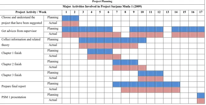
1.1 Gantt chart of PSM 1 activities ………... 6
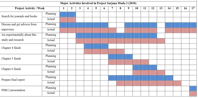
1.2 Gantt chart of PSM 2 activities ………... 7
3.1 List of apparatus for this experiment ………..……. 46
3.2 Example table of result ………....…… 50
LIST OF FIGURES
2.1 The backscattering technique ………..….………... 18
3.1 Flow chart of project ………….……….…...………..……... 32
3.2 Types of materials for cutting tool and coated layer (side-view) …...…… γ7 3.3 Tungsten carbide zooming at 25 X ………... γ8 3.4 Sintered tungsten carbide zooming at β5 X ………... 38
3.5 Geiger-Müller counter (GM counter) ……….…... 41
3.6 Geiger-Müller tube (GM tube) ………... 42
3.7 Example of radiation source ………..…………. 4γ 3.8 Vacuum PVD machine (model VTC PVD-1000) …………..………... 45
3.9 Methods preparation ………..………... 47
3.10 Distance and angle position preparation ………..…...……… 48
3.11 Graph of average intensity versus anodize coating thickness ……... 49
4.1 Graph of counts versus thickness for Sr-90 source ..………..……… 5γ 4.2 Graph of counts versus thickness for Co-60 source ….……..……… 54
4.3 SEM image for RUN 11 sample under 10 000x magnification ……….… 55
4.4 SEM image for RUN 1β sample under 10 000x magnification ……….… 55
4.5 SEM image for RUN 14 sample under 10 000x magnification ……….… 56
4.6 SEM image for RUN 16 sample under 10 000x magnification …….…… 56
4.7 SEM image for RUN 17 sample under 10 000x magnification ….……… 57
4.8 SEM image for RUN 18 sample under 10 000x magnification .………… 57
4.9 SEM image for RUN 19 sample under 10 000x magnification …….…… 58
LIST OF ABBREVIATIONS
Am-241 - Americium-241
AFM - Atomic Force Microscope
Co-60 - Cobalt-60
CrN - Chromium Nitride
CrTiAlN - Chromium Titanium Aluminium Nitride CVD - Chemical Vapor Deposition
ERDA - Elastic Recoil Detection Analysis
eV - Electron Volt
FEM - Finite Elements Method
GDOES - Glow Discharge Optical Emission Spectroscopy
GM - Geiger-Müller
HERDA - Heavy-Ion Elastic Recoil Detection Analysis IRE - Internal Reflection Element
kBq - Kilo-Becquerel
LIBS - Laser-Induced Breakdown Spectroscopy
PES - Proton Enhanced Scattering
PIXE - Proton Induced X-ray Emission
PSM - Projek Sarjana Muda
PVD - Physical Vapor Deposition RBS - Rutherford Backscattering
RCVD - Reactive Chemical Vapor Deposition
Sr-90 - Srontium-90
TiAlN - Titanium Aluminium Nitride
TiN - Titanium Nitride
UTeM - Universiti Teknikal Malaysia Melaka
UV - Ultraviolet
CHAPTER 1
INTRODUCTION
1.1 Background
The selection of cutting tool materials for a particular application is among the most important factors in machining operations, as is the selection of mold and die materials for forming and shaping processes. As noted in engineering technology, the cutting tool is subjected to several factors such as high temperatures, high contact stresses, and rubbing along the tool-chip interface and along the machined surface. Consequently, the cutting tool material must possess the criteria such as hot hardness, toughness and impact strength, thermal shock resistance, wear resistance and chemical stability. To respond to these demanding requirements, various cutting tool materials with a wide range of mechanical, physical, and chemical properties have been developed over the years.
The aim of applying coatings is to improve surface properties of a bulk material usually referred to as a substrate. Coatings have unique properties, such as lower friction, higher adhesion, higher resistance to wear and cracking, acting as a diffusion barrier, and higher hot hardness and impact resistance. Coated tools can have tool lives 10 times longer than those of uncoated tools, allowing for high cutting speeds and thus reducing both the time required for machining operations and production costs. As a result of widely usage, coated tools now are used in 40 to 80% of all machining operations, particularly in turning, milling, and drilling. Surveys have indicated that the use of coated tools is more prevalent in large companies than in smaller ones (David Beamish, 2001).
Commonly used as coating materials are titanium nitride (TiN), titanium carbide (TiC), titanium carbonitride (TiCN), and aluminum oxide (Al2O3). These coatings, generally in the thickness range of 2 to 15 µm, are applied on cutting tools and inserts by two techniques. The first technique is Chemical-vapor Deposition (CVD), including plasma-assisted chemical-vapor deposition and the second one is Physical-vapor Deposition (PVD). The CVD process is the most commonly used method for carbide tools with multiphase and ceramic coatings. The PVD-coated carbides with TiN coatings, on other hand, have higher cutting edge strength, lower friction, lower tendency to form a built-up edge, and are smoother and more uniform in thickness, which is generally in the range of 2 to 4 µm (Hiroaki Yamamoto, 1996).
maintenance of coating strength; otherwise, the coating may peel or chip off at sharp edges and corners (Andrew J. Slifka, 1999).
Coatings can be measured and tested for proper opacity and film thickness by using several of methods or techniques. The evaluation of coatings is an important part of the quality assurance process in many industries. It also enables the optimum use of material. A prerequisite for this is that coating thicknesses can be accurately measured. Of course this applies not only to coatings on metal parts but also to such coatings on base materials like wood, plastics, ceramic, glass, and others. Until now, sample analysis of unknown bulk material alloys or unidentified coatings has required certain knowledge of what to expect before accurate quantitative results could be obtained (Edgar Gutoff, 2001).
A variety of recognized methods can be used to determine the thickness of organic coatings. The method employed in a specific situation is most often determined by the type of coating and substrate, the thickness range of the coating, the size and shape of the part, and economics. Commonly used measuring techniques are nondestructive dry film methods such as magnetic, eddy current, ultrasonic or micrometer measurement; destructive dry-film methods such as cross-sectioning or gravimetric (mass) measurement; and wet-film measurement. However, in this PSM project, the technique or method that will be use is beta (β) thickness gauging method. The purpose of this project and research is to determine the thickness of cutting tool coating by using this kind of method, whereas it was using beta radiation as its source.
1.2 Problems Statement
The problems statement is to study the feasibility or practicability of beta (β) backscatter thickness measurement and measuring technique of tool machining. The advantage of this technique is measuring the cutting tool coating thickness in situ and no destruction of the tool to be measured.
1.3 Objectives of Project
The purposes of this project are:
i. To develop a method of measuring the coating thickness of cutting tool by using beta (β) gauging technique.
ii. To measure the cutting tool coating thickness by using backscattering technique from different type of beta radiation source.
1.4 Scope of Project
This research is about to study and determine the coating thickness of cutting tool, which was measured by using beta (β) thickness gauging method. Samples of cutting tool base material of sintered tungsten carbide coated with titanium aluminium nitride was prepared using the physical vapor deposition machine available in the Advance Manufacturing Centre, UTeM. The control variables in this measuring process are angle of source holder and distance between specimen and source. Value of cutting tool coating thickness was measured by using beta (β) scattering technique where the GM (Geiger-Muller) counter and the GM tube are used to measure the reflected Beta particle from the target material.
1.5 Report Outline
This report writing consists of three chapters for Projek Sarjana Muda (PSM) 1. Chapter 1 is describes about introduction; which is includes the project background, problem statement, objective of project, scope of project, and the importance of this study. Then the Chapter 2 stressed on the literature review of related issues and for Chapter 3, it was highlighted more towards the methodology of the project, which is includes the process planning for this project, flowchart, data gathering method, and analytical techniques in this project.
1.6 Gantt Chart of PSM
Below Gantt chart shows the planning and actual process in this project. Not all of the plans work properly as planned because of some technical problems.
Project Planning
Major Activities Involved in Project Sarjana Muda 1 (2009)
Project Planning
Major Activities Involved in Project Sarjana Muda 2 (2010)
Project Activity / Week 1 2 3 4 5 6 7 8 9 10 11 12 13 14 15 16 17
Search for journals and books Planning Actual
CHAPTER 2
LITERATURE REVIEW
2.1 Introduction
Coatings perform a variety of important functions including protecting and beautifying outdoor structures and manufactures goods. Accurately measuring the thickness of these coatings helps maintain product quality and control production costs. Several types of instruments are available to measure coatings in their uncured (wet) or cured (dry) state. Proper instrument selection is crucial to obtaining accurate, meaningful results. Instrument selection is dependent upon the type and thickness range of the coating, the substrate material, the shape of the part, and the need for statistical analysis. To make this choice, one must understand the different for coating thickness measurement. Below are attachments of journals in experimental about how the parameters are selected and the processes to determine the feasibility and practicability of this research.
2.2 Measurement of Coating Thicknesses
correspond to the thickness of the back side coating, and the reflection coefficient has a minimum value. The top surfaces of the samples are covered with a coating about γ0 m thick and the thickness of the back side coating is in the range of 10.3 – 17.5 m. The resonant frequencies for the examined samples are observed in the frequency range of 46.8 – 75.6 MHz, and the thickness of the back side coating can be accurately determined from the measured resonant frequency. The coating on the top surface of the structure does not affect the thickness measurement accuracy of the back side coating (Hironori Tohmyoh, Manabu Suzuki, 2009).
In measuring the thickness of protective coatings on historic metal objects using nanosecond and femtosecond laser induced breakdown spectroscopy depth profiling, it is show that the depth profile analysis by means of laser induced breakdown spectroscopy (LIBS) was investigated with respect to its potential to measure the thickness of different types of thin organic films used as protective coatings on historical and archaeological metal objects. For the materials examined, acrylic varnish and microcrystalline wax, the output from a nanosecond ArF excimer laser at 193 nm was found appropriate for performing a reliable profiling of the coating films leading to accurate determination of the coating thickness on the basis of the number of laser pulses required to penetrate the coating and on the ablation etch rate of the corresponding coating material under the same irradiation conditions. Nanosecond pulses at 248 nm proved inadequate to profile the coatings because of their weak absorption at the laser wavelength. In contrast, femtosecond irradiation at 248 nm yielded well-resolved profiles as a result of efficient ablation achieved through the increased non-linear absorption induced by the high power density of the ultrashort pulses (P. Pouli, K. Melessanaki, A. Giakoumaki, V. Argyropoulos, D. Anglos, 2005).
with resolution 160 eV at 5.9 keV. The thicknesses of the coating materials found by the scattered radiation have been compared with thicknesses found by the gravimetric method. The obtained results show that there is good agreement between the present experimental results and the values of the gravimetric method within the estimated experimental error (N. Ekinci, Y. Kurucu, E. Öz, Y. Sahin, 2002).
Measuring film thickness using infrared imaging show that an Infrared imaging was used to measure the thickness of a Krylon® flat black spray paint coating applied to the surface of steel test coupons. Thermal signals were generated in the test samples by applying a cyclic tensile load at various frequencies, which generated a corresponding thermo-elastic temperature change. Since the substrate is a better thermo-elastic generator than the paint, the heat generated in the metal conducts through the paint during each cycle of loading and is easily distinguished from the paint signal. Test samples were prepared with a stepped progression of controlled paint thickness, and infrared images taken using a Delta Therm 1000 IR imaging system. The infrared signal intensity as well as the phase lag relative to the applied loading was directly related to the paint thickness. The experimental results are described well using existing heat conduction models. Though the proposed method was proven using thermoelastic heating, any heat source below the paint can be used to provide the necessary reference signal. Furthermore, the method can also be used for any coating type and is not limited to paint coatings (Carrie A. Decker, Thomas J. Mackin, 2005).
excellent precision (i.e. with a standard deviation lower than ±1 m) and high time resolution (2.5 spectra/s) can be obtained (Katja Heymann, Gabriele Mirschel, Tom Scherzer, Michael R. Buchmeiser, 2009).
A digital instrument for nondestructive measurements of coating thicknesses by Beta backscattering shows the elements of nondestructive gauging of coatings applied on various metal bases. The intensity of the backscattered beta radiations is related to the thickness of the coating. With a fixed measuring geometry and radioactive sources (147Pm, 204Tl, 90Sr+90Y) the intensity of the backscattered beta particles is dependent on the following parameters: coating thickness, atomic number of the coating material and of the base, the beta particle energy and the surface finish. It can be used for the measurement of a wide range of coating thicknesses provided that the difference between the coating and the support atomic numbers is at least 20%. Fields of application include electronics, electrotechnique and so on (D. M. Farcasiu, T. Apostolescu, H. Bozdog, E. Badescu, V. Bohm, S. P. Stanescu, A. Jianu, C. Bordeanu, M. V. Cracium, 1992).
The research of online coating thickness measurement and depth profiling of zinc coated sheet steel by laser-induced breakdown spectroscopy state the study of new method for online analysis of the zinc coating of galvanized sheet steel based on laser-induced breakdown spectroscopy (LIBS). The coating is characterized with a series of single laser bursts irradiated on the traversing sheet steel, each on a different sheet steel position. To achieve an ablation depth in the range of the coating thickness of about 10
m a NdμYAG laser at 1064 nm in collinear double pulse mode was used. The depth
information is obtained by control of the ablation depth by adjusting the burst energy using an external electro-optical attenuator. Concepts for the determination of the coating thickness and the chemical composition are presented. The achieved thickness resolution is estimated to about 400 nm for coating thicknesses of electrolytic galvanized