Procedia Engineering 00 (2013) 000–000
The Malaysian International Tribology Conference 2013, MITC2013
Gnielinski method in calculating the heat transfer coefficient for metallic
solar tower absorber
Z.M. Zulfattah
a,*, S.A. Rafeq
a, Z.M. Shukri
a, J. Ridhwan
a, M.H.M. Hanafi
a, I. Norain
a, Z.N.
Huzaimi
a, M.I.N. Shakinah
a, A.M. Najib
baFakulti Kejuruteraan Mekanikal, Universiti Teknikal Malaysia Melaka, 75450, Ayer Keroh, Malaysia bFakulti Kejuruteraan Pembuatan, Universiti Teknikal Malaysia Melaka, 75450, Ayer Keroh, Malaysia
Abstract
This work is done to calculate the heat transfer coefficient of metallic wire mesh to air in an open volumetric thermal absorber. It is aimed to replace the actual ceramic with metallic which latter has better thermal properties in order to increase the efficiency of the concentrating solar power plant. The calculation of the heat transfer coefficient from porous wire structure to the air has been conducted to pursue the purpose. The structure that has been chosen is a set of metallic wires with aligned and shifted configurations. The variations of wire diameter together with various porosities from 0.10 to 0.50 have been calculated to obtain the best configuration for the absorber. The flow characteristic within the mesh structure in terms of Reynolds number and its relationship with the heat transfer coefficient has been obtained. The condition on mass flow rate of heat transfer medium and other aspects which influence the heat transfer are also discussed.
© 2013 The Authors. Published by Elsevier Ltd.
Selection and peer-review under responsibility of The Malaysian Tribology Society (MYTRIBOS), Department of
Mechanical Engineering, Universiti Malaya, 50603 Kuala Lumpur, Malaysia.
Keywords: porous metallic absorber; ceramic absorber; porosity; heat transfer coefficient; concentrating solar power
Nomenclature
0
m
Mass flow rate of air [kg/s]
θin Air inlet temperature [°C]
θout Air outlet temperature [°C]
θm Mid temperature [°C]
θw Front absorber temperature [°C]
θA Tail absorber temperature [°C]
w Flow velocity in the matrix [m/s]
Dimensionless character
xx Re
Reynolds number
Greek symbols
α Heat transfer coefficient [W/m²K]
ψ Fraction of hollow space
* Muhammad Zulfattah Zakaria. Tel.: +6-06-234-6796; fax: +6-06-234-6884.
Latin alphabets
da Wire diameter [m]
s1 Wire pitch [m]
L Length of absorber cup [m]
w Width of absorber cup [m]
d Depth of absorber cup [m]
a Ratio s1/da
z Wire/row
s2 Distance between rows [m]
b Ratio s2/da
S Stream cross-sectional area in front of absorber [m²]
l Length of wire facing stream [m]
P Porosity
n Number of layers of metal mesh above one another
Pt Transverse pitch [m]
rh Hydraulic radius / effective length across wire matrix [m]
A Heat transfer area [m²]
av Surface area density [1/m]
mmesh Mass of wire mesh [kg]
1.Introduction
Concentrating Solar Tower (CST) is an advanced solar energy collecting system used to harness solar thermal energy. Solar energy is reflected by a field of heliostat and the concentrated sun ray which may reach to a factor of 600 to 1000 hits the collector or receiver located at the top of the tower [1]. This dense energy heats up the receiver rapidly and thus the most suitable material for the receiver or absorber is ceramic-based. Ceramic is a low thermal conductivity material which hinders higher power plant thermal efficiency. Action has been taken to replace the ceramic to a metallic material which has better heat transfer capability. This new metal-based absorber will be deployed at the circumference of the gigantic absorber frame where operating temperature is the lowest and suitable for metal to survive. The idea is to use wire mesh packed in the absorber cup to maximize the surface area but at an optimal porosity to avoid unnecessary load on blower unit [2-3].
Sintered porous structure which behaves like a micro mesh has been successfully used in a low temperature cryogenic application [4] while Kempers et. al. [5] applied the wire screen mesh for heat exchanger. As wire mesh is widely used in heat transfer application this research has been carefully conducted to examine whether it is also suitable for the absorber structure in CST application. The porous wire screen has been chosen as a candidate for the absorber of the CST. The work is started with measuring the size of the absorber cup, absorber structure and other parameters as shown in Table 1:
Table 1. Absorber cup and absorber dimension (source: Solar Institute Juelich, SIJ)
Dimension of cup and absorber structure
Length, L [m] 0.14
Width, w [m] 0.14
Depth, d [m] 0.03
Surface area, A [m2] 0.0196
Volume, V [m3] 0.000588
Total absorber surface area, A_f(tot) [m2] 22
2.Selection of wire mesh
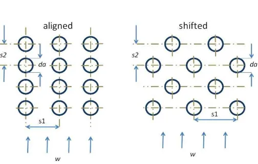
Calculation is started with two possible wire configurations as stated by Gnielinski in the GG section which are aligned and shifted configurations [6]. Porosity for both configurations can be calculated using Eq. (1) [7]:
2
2.1.Aligned and shifted configurations
The calculation started by calculating the fraction of hollow space, ψ (Greek: Psi) and it is dependent on the value of b
which is defined as ratio of distance between layers over wire diameter, s2/da.
for b≥1 1/(4a) (2)
for b≤1 1/(4ab) (3)
The arrangement of tubes is then divided into two groups. One is aligned and the other is shifted. The distance between tubes in a row, s1 and the distance between rows of layers, s2 are constants and defined as:
da
Fig. 1. Proportionally aligned and shifted configuration of bundle of tubes
2.2.Presetting the shifted configuration
The operation temperature and also the set of wire mesh of the absorber are set primarily to follow the values given by Prasad et. al. [2] in order to examine the formula. After confirming that the formulas are giving the correct values the parameter of the wire mesh is then changed to the desired value for the CST absorber.
The best heat transfer occurs in the least porous structure. Therefore, calculations started at fraction of hollow space ψ of
only 0.1 which means 90 percent of the cup volume is empty. Relative mass flow rate G0 of 0.5455 kg/m.s2 as well as other
parameters listed on the left of the table below are the actual air parameters during operation. The corresponding air properties are listed on the right (Table 2).
Table 2. Operating condition and the corresponding air properties
Flow characteristics like Reynolds number, Nusselt number and also Prandtl number have been inserted into the program to calculate and simulate the real condition.
3.Results and discussion
1.00E-03 1.10E-03 1.20E-03 1.30E-03 1.40E-03 1.50E-03 1.60E-03 1.70E-03
H
0.0010 0.0011 0.0012 0.0013 0.0014 0.0015 0.0016 0.0017
H
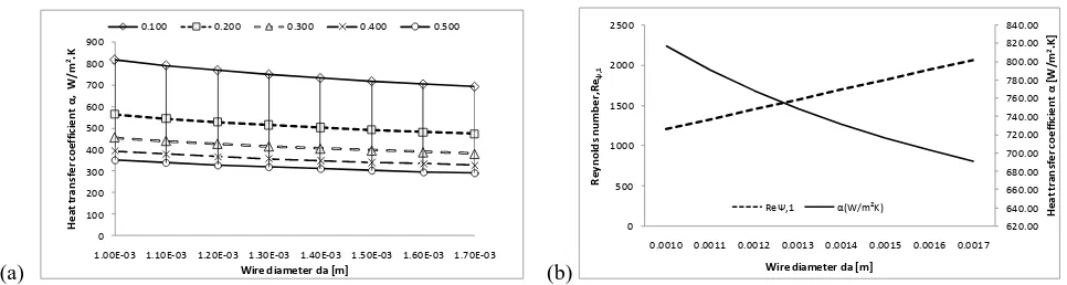
Fig. 2. Results using six layers of wire mesh with porosity from 0.1 to 0.5 for (a) wire diameter versus heat transfer coefficient α and (b) wire diameter
versus Reynolds number with corresponding α.
Fig 2(a) shows that the increasing amount of wire inside the absorber cup leads to a less porous structure which reduces
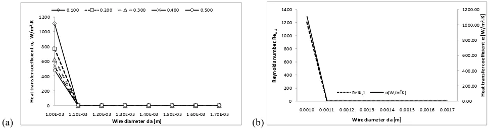
the heat transfer ability. Increasing the layer leads to a higher α which is good for the absorber cup. The best α of 1111
W/m2.K has been recorded for 1mm wire diameter with 24 mesh layers and ψ equals to 0.1, see Fig 3.
Reynolds number is recorded increasing with the diameter of the wire mesh used. Bigger wire reduces the porosity ψ and
(a)
1.00E-03 1.10E-03 1.20E-03 1.30E-03 1.40E-03 1.50E-03 1.60E-03 1.70E-03
H
0.0010 0.0011 0.0012 0.0013 0.0014 0.0015 0.0016 0.0017
H
Fig. 3. Results using 24 layers of wire mesh with porosity from 0.1 to 0.5 for (a) wire diameter versus heat transfer coefficient α and (b) wire diameter
versus Reynolds number with corresponding α.
4.Conclusion
There is a small possibility that the wire mesh will be placed unevenly during production but the uneven placement of tubes in the bundle is not entertained in this task as the deviation is neglected at this early stage. The calculations to obtain the relationship of wire mesh candidates with Prandtl number, volumetric heat transfer and also effect of cyclic load on the elongation of the wire itself must be conducted.
As we can see the best heat transfer coefficient α comes with the smallest wire diameter and also the least porous structure. Small wire tends to bend more easily under load compares to the bigger wire. Bending of wire will eventually clog the entrance and destroy the absorber. The application itself which involves cyclic thermal loads and thermal shock will just accelerate the process. Therefore more calculations and experiments are necessary in order to choose the best material, wire size and coordination which can withstand the harsh working condition. The wise choice will make the structure to run at the optimum performance and simultaneously keep the maintenance at the longest interval.
Acknowledgements
Authors gratefully acknowledge the financial support for this project under the Short-Term Grant PJP/2012/FKM(59A) S1066 from Universiti Teknikal Malaysia Melaka (UTeM).
References
[1]F. and F. T. Hans Mueller Steinhagen, “Concentrating solar power - A review of technology,” Stuttgart, Germany.
[2]S. B. Prasad, J. S. Saini, and K. M. Singh, “Investigation of heat transfer and friction characteristics of packed bed solar air heater using wire mesh as
packing material,” Solar Energy, vol. 83, no. 5, pp. 773–783, May 2009.
[3]C.-D. Ho, C.-S. Lin, Y.-C. Chuang, and C.-C. Chao, “Performance improvement of wire mesh packed double-pass solar air heaters with external
recycle,” Renewable Energy, vol. 57, pp. 479–489, Sep. 2013.
[4]C. Shuangtao, H. Yu, Z. Hongli, and X. Lan, “A numerical model of thermal analysis for woven wire screen matrix heat exchanger,” Cryogenics, vol. 49, no. 9, pp. 482–489, Sep. 2009.
[5]R. Kempers, A. J. Robinson, D. Ewing, and C. Y. Ching, “Characterization of evaporator and condenser thermal resistances of a screen mesh wicked heat pipe,” International Journal of Heat and Mass Transfer, vol. 51, no. 25–26, pp. 6039–6046, Dec. 2008.
[6]Verein Deutscher Ingenieure, VDI-Waermeatlas, 10th ed. Springer, 2006.