SUPERVISOR DECLARATION
“I hereby declare that I have read this thesis and in my opinion this report is sufficient in terms of scope and quality for the award of the degree of Bachelor of
Mechanical Engineering (Automotive)”
Signature : ……… Supervisor : MR. FAUZI BIN AHMAD
ACTIVE SUSPENSION CONTROL OF GROUND VEHICLE HEAVE AND PITCH MOTION
ii
ACTIVE SUSPENSION CONTROL OF GROUND VEHICLE HEAVE AND PITCH MOTION
ASOK MAX A/L SUBRAMANIAM
This report is submitted in partial fulfillment of the requirement for Degree of Bachelor in Mechanical Engineering (Automotive)
Faculty of Mechanical Engineering Universiti Teknikal Malaysia Melaka
iii
DECLARATION
“I hereby declare that the work in this report is my own except for summaries and quotations which have been duly acknowledged.”
Signature : ………..………. Author : ………...
iv
v
ACKNOWLEDGMENT
Praise to God almighty for His grace in providing me the strength and ability in bringing this research to completion.
I would like to extend my sincere gratitude and appreciation to my project supervisor, Mr. Fauzi Bin Ahmad, for his devotion and effort in providing me with the guidance needed to accomplish this research. I am also indebted to Mr Amrik Singh, my first panel, who helped in the completion of this thesis. Last but not least, my appreciation is also to Mr. Vimal, who guided me in conducting the simulation throughout the course of this research.
vi
ABSTRACT
Vehicle in motion experience unwanted motion such as heave and pitch motion due to driver input and road irregularities. Heave motion refers to the
vehicles vertical displacement and the pitch motion refers the angular moment in the longitudinal direction of the vehicle. Active suspension system uses a feedback
vii
ABSTRAK
Sebuah kenderaan yang bergerak akan mengalami gerakan kenderaan yang tidak di ingini seperti jonketan dan getaran disebabkan oleh permukaan jalan raya yang tidak sekata dan juga kerana input dari pemandu. Getaran merujuk kepada sesaran badan kenderaan di arah atas dan ke bawah, manakala getaran kenderaan merujuk pada momen sudut kenderaan tersebut. Sistem suspensi aktif mengunakan sistem kawalan berbalik intuk mengurangkan kesan getaran dan jongketan pada kenderaan dengan mengunakan daya dari penggerak pada sistem suspensi. Sebelum ini dalam strategi kawalan untuk sistem suspensi aktif, pengawal PID telah di gunakan, dan untuk menambahbaik prestasi dan kecekapan strategi kawalan, pengawal yang baru diperkenalkan, iaitu pengawal fuzzy logic. Model matematik yang mewakili sistem suspensi separuh kenderaan di terbitkan, dan berikutan itu dimodelkan dalam perisian MATLAB Simulin. Dengan menggunakan model kenderaan tersebut, satu strategi kawalan menggunakan pengawal PID dan satu lagi
viii
TABLE OF CONTENT
CHAPTER TITLE PAGE
DECLARATION iii
ACKNOWLEDGMENT v
ABSTRACT vi
ABSTRAK vii
LIST OF TABLE x
LIST OF FIGURES xi
LIST OF SYMBOLS xiii
LIST OF APPENDICES xv
CHAPTER 1 INTRODUCTION 1
1.1 Introduction 1
1.2 Background 1
1.3 Problem Statement 2
1.4 Objective 2
1.5 Scope of Project 2
1.6 Thesis Outline 3
CHAPTER 2 LITERATURE REVIEW 4
2.1 Introduction 4
2.2 Vehicle Suspension System 4
2.3 Active Suspension System 6
2.3.1 Control Scheme Used in Previous Studies 8
2.4 PID Controller 10
ix
2.6 Modeling Assumption 13
2.7 Four Degree of Freedom (4DOF) Vehicle Model
for Heave and Pitch Motion
13
2.8 Decoupling Transformation 19
CHAPTER 3 METHODOLOGY 21
3.1 Introduction 21
3.2 Mathematical Equation Derivation 21
3.3 MATLAB Simulink Modeling 22
3.3.1 4-DOF Vehicle Model 22
3.3.2 Decoupling Transformation Model 25
3.3.3 PID Control Model 26
3.3.4 PID Control Model 28
CHAPTER 4 RESULTS AND DISCUSSION 34
4.1 Introduction 34
4.2 Vehicle Body’s Vertical Displacement 35 4.3 Vehicle Body’s Pitch Angle 37
4.4 Suspension Deflection 40
4.5 PID Controlled Strategy Response 44
4.6 Fuzzy Logic Controlled Strategy Response 45 4.7 Comparison of the Control Strategies 46
CHAPTER 5 CONCLUSION 47
5.1 Conclusion 47
5.2 Recommendation 47
REFERENCES 48
x
LIST OF TABLE
NO. TITLE PAGE
xi
LIST OF FIGURES
NO. TITLE PAGE
2.1 Vehicle suspension System 5
2.2 The active suspension system 7
2.3 Closed loop control scheme of the time separation method 9 2.4 Active filtered feedback control system 10
2.5 Block of the PID controller 11
2.6 Fuzzy logic structure model 12
2.7 4 DOF pitch plane vehicle model. 14
2.8 The free body diagram of the 4 DOF pitch plane vehicle model
14
2.9 Sprung mass position due to pitching motion 16 2.10 Pitch moment due to vehicle acceleration 18
2.11 The active suspension system 19
3.1 Subsystem of the 4 DOF passive suspension system 22
3.2 Road Bump Profile 24
3.3 Time delay between the front and rear wheel road input 25 3.4 MATLAB Simulink model of the decoupling
transformation Equation
25
3.5 The MATLAB Simulink model of 4 DOF active
suspension vehicle model using the PID controller
27
3.6 The MATLAB Simulink model of 4 DOF active
suspension vehicle model using the Fuzzy Logic controller
28
3.7 Fuzzy Logic Control module. 29
3.8 The Fuzzy Inference System editor. 29
xii
3.10 Membership function plot for error signal 30 3.11 Membership function plot of the error rate signal 30
3.12 Fuzzy logic rule base surface 32
3.13 The Passive, PID active and Fuzzy active suspension
system control structure.
33
4.1 Vehicle vertical displacement of passive, PID controlled
and Fuzzy Logic controlled suspension system
36
4.2 Comparison of the vehicle vertical displacement of passive, PID controlled and Fuzzy Logic controlled suspension System
37
4.3 Vehicle pitch angle of passive, PID controlled and Fuzzy Logic controlled suspension system.
38
4.4 Comparison of vehicle pitch angle of passive, PID controlled and Fuzzy Logic controlled suspension system
39
4.5 Front suspension deflection of Passive suspension system, PID controlled active suspension system and Fuzzy controlled active suspension system
41
4.6 Front suspension deflection 42
4.7 Rear suspension deflection of Passive suspension system, PID controlled active suspension system and Fuzzy
controlled active suspension system
43
xiii
LIST OF SYMBOLS
= Distance if the Front Axle from C.G. = Distance of the Rear Axle from C.G.
= Front Suspension Damping
= Rear Suspension Damping = Front Actuator Force
= Front Actuator Force
= Force Exerted by the Front Damper = Force Exerted by the Rear Damper
= Force Exerted by the Front Spring
= Force Exerted by the Rear Spring = Force Exerted by the Front Wheel
= Force Exerted by the Rear Wheel = Vertical Force
= Height of C.G. from the Ground = Moment of Inertia of Pitch
= Front Suspension Spring Stiffness = Rear Suspension Spring Stiffness
= Front Tire Spring Stiffness
= Rear Tire Spring Stiffness = Mass of Vehicle Body = Pitch Moment
= Mass of the Front Wheel = Mass of the Rear Wheel
xiv
= Positive = Positive Big = Positive Small
= Time
= Settling Time
= Longitudinal Acceleration of the Vehicle = Zero
= Body Vertical Acceleration = Front Body Vertical Displacement
= Rear Body Vertical Displacement
= Front Body Vertical Velocity = Rear Body Vertical Velocity
= Front Wheel Vertical Displacement
= Rear Body Vertical Displacement
= Front Wheel Vertical Velocity = Rear Wheel Vertical Velocity = Front Wheel Vertical Acceleration = Rear Wheel Vertical Acceleration
= Pitch Angle
xv
LIST OF APPENDICES
APPENDIX TITLE PAGE
Figure A MATLAB Simulink model of 4 DOF passive suspension vehicle model
51
Figure B Passive suspension system, PID controlled active suspension system, Fuzzy logic controlled active suspension system, MATLAB Simulink model
comparison
52
1
CHAPTER 1
INTRODUCTION
1.1 INTRODUCTION
This chapter describes the background of active suspension control of ground vehicle heave and pitch motions. Next, the problem statement of this study and the objective of the project are explained. Following that, the scope of the project is mentioned and finally this chapter is ended with the outline of the Thesis.
1.2 BACKGROUND
2
1.3 PROBLEM STATEMENT
Vehicle in motion experience unwanted motions such as heave and pitch motion due to the road conditions. The pitch motion also occurs during sudden braking or sudden acceleration of the vehicle. This uncontrollable motion of the vehicle will cause the vehicle to vibrate resulting in driving discomfort and poor vehicle handling.
By applying the active suspension control system, the vibrations and unwanted motions of the vehicle due to road irregularities can be significantly reduced, improving driving comfort.
1.4 OBJECTIVE
The objective of this study is to develop a control strategy for vehicles active suspension system control unit by using the fuzzy logic controller.
1.5 SCOPE OF PROJECT
3
1.6 THESIS OUTLINE
4
CHAPTER 2
LITERATURE REVIEW
2.1 INTRODUCTION
In this chapter the passive suspension system of a conventional vehicle is discussed together with the active suspension system. In this chapter also discussed the controllers that are used in the active suspension control strategy. The modeling assumptions are discussed and the mathematical model for the half car pitch plane model is derived. The chapter is concluded with the derivation of the equation for the decoupling transformation.
2.2 VEHICLE SUSPENSION SYSTEM
5
The suspension system provides a vertical counterforce to compensate the forces experienced by the wheels due to the uneven road terrain, in order to isolate
[image:21.595.139.500.276.512.2]vibrations the vehicles chassis. The suspension also helps to well maintain the steer and the camber settings of the wheels to the road profile. The suspension responds to the control forces that are produced by the tires longitudinal forces due to acceleration and braking, lateral forces due to cornering and driving torques. The suspension of the vehicle also functions to resist the roll moment of the car due to cornering, and maintaining the wheels contact to the ground at all times (Gillespie 1992).
Figure 2.1: Vehicle suspension System (Source: Wood, 2009)
The performance of a vehicles suspension system is rated based on the vehicles ability to provide better road handling and improved passenger ride comfort. The comfort of the passenger depends mostly on the combination of vehicles vertical
motion (heave motion) and the angular motions of the vehicle (pitch and roll motion). Present vehicle suspension system which uses passive components can offer
6
much softer suspension in order to provide better passenger comfort, but softer suspension reduces the vehicle driving performance. Poor vehicle performance due
to road profile and reduced in passenger comfort are caused by the excessive vehicle vibrations which as a consequence results artificial speed limit, decrease in vehicle frame durability, effects the passenger in term of biological and also damages the cargo (Ikenaga et al. 2000).
It has been a major challenge in vehicle design in order to reduce the vehicle vibration caused by uneven road conditions and to improve the vehicles quality in terms of handling and comfort (Lin et al. 1992). Over the years since the start of automotive era, many types of vehicle suspension has been developed, which uses numerous kinds of springs, dampers and linkages with custom made flexibility. The most common and simplest type of suspensions are the passive suspensions, which does not require external energy source, but passive suspension does not control the heave and pitch motions of the vehicle independently (Campos. et al. 1999). Efforts has been taken to conduct research that would improve the vehicle suspension system, and the results show that the only way to improve vehicles performance in providing better handling and drive control is by adding external force which would provide a counter force that compensates to the forces on the wheel.
2.3 ACTIVE SUSPENSION SYSTEM
7
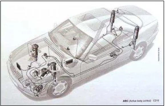
Active suspension system is a normal suspension system added with independent actuators on each wheel. Actuators are fitted in parallel to the
[image:23.595.175.464.360.546.2]suspension system between the vehicle body and the wheel. The actuators utilize the space between the wheel and the body to pull and push the vehicle body in order to minimize the vibration caused by the road irregularities (Pekgökgöz et al. 2010). These actuators act as to improve the vehicles passive suspension system response towards vibration and handling. Actuators exert force on the suspension system through a feedback control system that interprets the real time information obtained from the sensors (McGinn and Geraghty 2010). Figure 2.2 shows an active suspension vehicle that fitted with sensors that monitor the vehicles body position, and four hydraulic actuators at each strut of the vehicle, controlled by the pressure from the hydraulic pump. The pump increases and decreases the pressure in the strut based on the information fed by the microcomputer.
Figure 2.2: The active suspension system (Source: Adams, 2011)
8
The actuators response to the information sent by the central unit, where the controller is located. Many types of controllers are used in the design of active
suspension system, and each controller has its own effectiveness in interpreting the data sent by the sensors and produces signal to the actuators. PID controllers are one type of controller that has been used in previous approach in the design of the control structure for active suspension system. Besides PID there are also other types of controller that are being introduced to improve the efficiency of the system, and to minimize the errors.
The active suspension system of a vehicle significantly improves the vehicles performance compared to a passive suspension system in terms of handling and ride comfort.
2.3.1 Control Scheme Used in Previous Studies
A control strategy using the time scale separation method has been conducted previous studies (Campos et al. 1999). The inner loop of this control scheme rejects the disturbance from the terrain, while the output loops are function to stabilize the heave and pitch motion experienced by the vehilcle. Decoupling transformation is