Application of ANFIS in predicting TiAlN coatings flank wear
1
A.S.H. Basari,
1,4A.S.M. Jaya,
2M.R. Muhamad,
3M.N.A. Rahman
1Fac. of Information & Communication Tech., 2
Centre of Graduate Studies, 3Fac. of Manuf. Eng. Universiti Teknikal Malaysia Melaka Hang Tuah Jaya, 76100, Durian Tunggal,
Melaka, Malaysia
[email protected], [email protected], [email protected], [email protected]
4
S.Z.M. Hashim,
4H. Haron
4Soft Computing Research Group (SCRG) Fac. of Computer Sciences & Information System
Universiti Teknologi Malaysia 81310, UTM, Skudai
Johor, Malaysia
[email protected], [email protected]
Abstract— In this paper, a new approach in predicting the flank wear of Titanium Aluminum Nitrite (TiAlN) coatings using Adaptive Network Based Fuzzy Inference System (ANFIS) is implemented. TiAlN coated cutting tool is widely used in machining due to its excellent resistance to wear. The TiAlN coatings were formed using Physical Vapor Deposition (PVD) magnetron sputtering process. The substrate sputtering power, bias voltage and temperature were selected as the input parameters and the flank wear as an output of the process. A statistical design of experiment called Response Surface Methodology (RSM) was used in collecting optimized data. The ANFIS model was trained using the limited experimental data. The triangular, trapezoidal, bell and Gaussian shapes of membership functions were used for inputs as well as output. The results of ANFIS model were validated with the testing data and compared with fuzzy rule-based and RSM flank wear models in terms of the root mean square error (RMSE), co-efficient determination (R2) and model accuracy (A). The result indicated that the ANFIS model using three bell shapes membership function obtained better result compared to the fuzzy and RSM flank wear models. The result also indicated that the ANFIS model could predict the output response in high prediction accuracy even using limited training data.
Keywords- ANFIS technique; flank wear; TiAlN coatings; PVD magnetron sputtering
I. INTRODUCTION
In high-speed machining process, the cutting tool is consistently dealing with high localized stress at the tool tip and high temperature which exceeds 800°C. In this process too, the cutting tool slides off the chip along the rake face and the newly cut workpiece surface [1]. These conditions are causing tool wear, reducing the cutting tool performances and quality of parts and deteriorating the tool life. The tool wear problem also could be influenced by workpiece material, cutting interface, cutting tool performance and geometry, and machine condition. In addition, tool wear condition has a direct effect on the economics of cutting operations, final product quality and process reliability [2]
Meanwhile, the cutting tool with high resistance wear promises better tool life and directly reduces machining cost. This performance could be enhanced by applying the thin film coating on the cutting tool. The main purpose of the thin film coating application is to improve the tool surface properties while maintaining its bulks properties. The performance of the coated tool has been proven in wear mechanism [3], hardness and adhesion [4] and tool life [5]. It is also has been ascertained that the coated tool is forty times better in tool wear performance compared to the uncoated tools [6]. This finding promises prolonging of tool life and enables the implementation of minimum liquid lubrication to reduce cost of coolant that makes up 16 to 20% of manufacturing cost [7]. This finding too contributes in minimizing environmental impacts produced by discarding of cutting fluid [8].
Physical Vapor Deposition (PVD) coating process plays essential roles in order to make the cutting tool perform better. It has been selected as a main coating process in hard coating purposes. However, two main challenging issues that need to be encountered in the coating process are cost and customization. The challenge to ensure reasonable cost in the process of coating and efficient process of treatment should be well-addressed as it directly affects the cutting tool market value [9]. Besides the equipment maintenance, other reasons that lead to high machining costs are the material usage and labor and the number of trial-and-error experiment. The new application of coating to the other process such as drilling and milling also are causing other trial and error experiments so that it could suit the parameters with the material used. Therefore, many researchers have developed models to address the coating process issues. Model development reduces resources wastage such as materials, equipment utilization, human resources and working time related to the trial and error experiments run.
work. Various techniques such as design of experiment [10], neural network [11], fuzzy logic [12] and Adaptive Network Based Fuzzy Inference System (ANFIS) have been applied. The design of experiment approaches like Taguchi, full factorial and Response Surface Methodology (RSM) are widely used to collect optimum and minimum experimental data [13].
The ANFIS model is trained by using actual experimental data. Then, the rules can be modified by expert. The ANFIS has been proven to be well-suited for modeling nonlinear industrial processes such as end-milling [14, 15], welding [16], water jet machining [17] and wire electrical discharge machine (WEDM) [18] . In view of the nonlinear conditions of a the magnetron sputtering coating process, the ANFIS model is employed for predicting the flank wear value of TiAlN coatings. So far, there is no study has been carried out on application of ANFIS technique for predicting the flank wear of TiAlN coatings. The main purpose of this study is to investigate the application of ANFIS model for predicting the flank wear of TiAlN coatings by using limited number of experimental data. Part II explains how the experimental data was collected. Part III describes how the ANFIS modeling was done. Part IV indicates and discuss the result of the study.
II. EXPERIMENTAL DETAILS
A. Material and Method
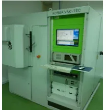
In this study, the experiment was run in unbalanced PVD magnetron sputtering system made by VACTEC Korea model VTC PVD 1000. Fig. 1 shows the PVD magnetron sputtering system. The coating chamber has two vertically mounted TiAl alloys which were selected as coating material. The chemical compositions of the TiAl alloy were titanium and aluminum with even percentage. The cutting tool inserts were hold in substrate holders with adjustable planetary rotation.
Figure 1. PVD unbalanced magnetron sputtering system VACTEC Korea model VTC PVD 1000.
Before the coating process, the surface of tungsten carbide cutting tool insert was cleaned with alcohol bath in an ultrasonic cleaner. After a 20- minute-bathing, the substrates were dried and then loaded in the rotating substrate holder. The rotation speed was set at 5 rpm. Then,
an inert gas, Argon was pumped into the chamber with controlled gas pressure. Argon was used to produce electron. The nitrogen gas was also pumped in as a reactive gas. The substrate was coated with the alloy in the presence of nitrogen gases.
The coating process consisted of substrate ion cleaning, deposition of interlayer coating of TiAl and deposition of TiAlN coating. In order to produce better adhesion, the impurity on the substrate surface was removed through the substrate ion cleaning process. The coefficient of thermal expansion gradient between the insert and TiAlN coatings was minimized through the interlayer coating deposition of TiAl. Then, the coating process was done in the presence of nitrogen gas to produce TiAlN. The detail process settings of the three stages are shown in Table I. A design of experiment technique called Response Surface Modeling (RSM) centre cubic design using Design Expert software version 7.03 was used to develop the experimental matrix. After the experiment, the influences of sputter power, bias voltage and substrate temperature on the coating flank wear were analyzed.
TABLE I. THE EXPERIMENT SETTING
Process Substrate ion
cleaning
Interlayer coating deposition
TiAlN deposition
Argon pressure (mbar): N2 pressure (mbar):
Ion source power (kV/A): Substrate bias (V): Duration (mins):
5.5 x 10⁻³ - 0.24 / 0.4 -200 30
4.0 x 10⁻³ - 0.24 / 0.4 -200 5 (0.2 µm)
4.0x 10⁻³ 0.4 x 10⁻³ 0.24 / 0.4 -50-300 90
B. Flank Wear Measurement
Figure 2. GATE-Precision milling machine and lathes model G-410-TCV
wear from the experiment. Table III shows the flank wear values of the machined coated cutting tools.
TABLE II. DETAILS OF TURNING PROCESS
Item Details Process
Workpiece material Machine type Feed rate, (mm/rev) Depth of cut, (mm) Cutting speed, (m/min) Fixed cutting length (m)
Dry turning D2 X115Cr VMo121 steel MAMOC lathe model SM200 0.26 1.6 200 18
Figure 3. Flank wear on the coated tool (white arrow)
TABLE III. PROCESS PARAMETERS AND EXPERIMENTAL RESULT OF
TIALNCOATINGS FLANK WEAR
Run Process variables Result
Sputter Power
(kW)
Bias Voltage
(Volts)
Substrate Temp.
(°C)
Flank Wear (mm)
1 6.00 50.00 400.00 2.29
2 4.81 100.67 518.92 1.08
3 4.81 249.33 281.08 0.73
4 6.00 175.00 400.00 1.40
5 6.00 175.00 200.00 0.94
6 4.81 100.67 281.08 2.01
7 7.19 249.33 281.08 1.92
8 6.00 175.00 400.00 0.57
9 6.00 175.00 400.00 1.26
10 4.81 249.33 518.92 1.97
11 7.19 100.67 281.08 1.18
12 6.00 175.00 600.00 1.72
13 7.19 249.33 518.92 0.35
14 6.00 175.00 400.00 0.86
15 8.00 175.00 400.00 0.27
16 6.00 300.00 400.00 1.03
17 7.19 100.67 518.92 0.93
18 4.00 175.00 400.00 0.56
19 6.00 175.00 400.00 0.85
20 6.00 175.00 400.00 0.83
III. ANFISMODELING
Adaptive Network Based Fuzzy Inference System (ANFIS) was presented by Jang in 1993 [19]. In this system, a hybrid learning procedure is used to construct an input-output mapping based on the human knowledge and training data pairs. The fuzzy inference system is employed in the framework of adaptive networks. ANFIS is normally contains a five-layer feed forward neural network excluding inputs to construct the inference system. Each layer consists of several nodes described by nodes function. The nodes in previous layer feed input to nodes in next layer.
Figure 4. The ANFIS structure with five layers and nodes [20]
The Fig. 4 illustrates the structure of ANFIS with five layers. To illustrate the procedures of an ANFIS, it is assumed that the system has two inputs (x1, x2) and one output (y). The ANFIS rules based contains fuzzy if-then rules of Sugeno type. The rules can be stated as:
Rule 1: If x is A1 and y is B1 then z is f1(x,y) Rule 2: If x is A2 and y is B2 then z is f2(x,y)
where x and y are the inputs of ANFIS, A and B are the fuzzy sets fi (x, y) is a first order polynomial and represents the outputs of the first order Sugeno fuzzy inference system.
TABLE IV. PARAMETERS SETTING FOR ANFISMODEL ANFIS Setting Details
Input Variables Output Response Input MFs Type
No. of MFs Output MFs Type Optimization Method
Epochs
Power, Voltage, Temperature Flank Wear
Triangular, Trapezoidal, Bell, and Gaussian
2,3 and 5
Constant and linear
Hybrid of the least-squares and the back propagation gradient descent method.
100
shape of input membership function (MFs) type which were triangular, trapezoidal, bell and Gaussian shapes, with number of the MFs were two, three and five. In purpose of training the model, a hybrid of the least-squares method and the back propagation gradient descent method was used to emulate a given training data set. The constant and linear of output MFs type were employed to produce the flank wear value. The details of model setting is shown in Table IV. The details of ANFIS model is shown in Table V.
TABLE V. DETAILS OF ANFISMODEL
ANFIS Info Number of nodes: 78 Number of linear parameters: 108 Number of nonlinear parameters: 27
Total number of parameters: 135 Number of training data pairs: 20 Number of checking data pairs: 3
Number of fuzzy rules: 27
IV. RESULT AND DISCUSSION
After the training process, the initial membership functions for input variables were derived by training. Fig. 5 (a)-(c) show the initial of MFs, while Fig. 5 (d)-(f) show the final MFs of the constant output.
(a) (d)
(b) (e)
(c) (f)
Figure 5. The MFs for the input variables before (a-c) and after (d-f) training
From the figures, a major change obviously can be seen on the shape of POWER membership function after the training process. Otherwise, the membership functions of the VOLTAGE and TEMPERATURE indicated only a slight changes. Fig. 6 shows the convergence of the ANFIS training. Meanwhile, the RMSE became steady after 2 epochs. The limited number of data cause the converging process is very fast and steady in that epoch.
0 20 40 60 80 100
Figure 6. Convergence of ANFIS training
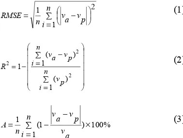
To verify the performance of the proposed ANFIS model, the following measures were used. The root mean squared error (RMSE) in (1) was used to quantify the difference between predicted and actual values. Meanwhile, the co-efficient determination (R2) in (2) was calculated in order to see how well the future output response is likely to be predicted by the model. Lastly, the prediction accuracy (A) in (3) was computed to determine the accuracy of the models.
where
n
is number of testing data,v
ais experimental valueand
v
pis predicted value.function (triangular, trapezoidal, Gaussian and bell) and different number of membership function (2, 3 and 5).
TABLE VI. VALIDATING DATA
Testing Power
(kW)
Table VIII shows the RMSE, R2 and prediction accuracy of the ANFIS models. The result shows that most of the models with linear output indicate less RMSE, and higher in R2 and A compared to the model with constant output.
TABLE VIII. RMSE,R2
AND MODEL ACCURACY FOR THE ANFIS MODELS
MFs Linear Constant
RMSE R2 A(%) RMSE R2 A(%)
Meanwhile, the model that used 3 bell MFs in the input variables indicates the highest prediction accuracy with 98.09%. On the other hand, the model with 3 Gaussian MFs shows the smallest RMSE with 0.032. However, both models show the same R2 with 0.999. The smooth shapes of the Gaussian and bell MFs helps in variant of fuzzy surface.
Besides that, Table IX shows the comparison of 3 bell MFs of ANFIS model with fuzzy and RSM flank wear model [21] in terms of RMSE, R2 and prediction accuracy. The comparison used same types and number of input variables. From the table, the ANFIS model indicates better performances compared to the other models to predict the flank wear.
Besides that, Fig. 7 shows agreement between actual and predicted wear value of the ANFIS, fuzzy and RSM models. The Fig. 7 shows that the predicted values of ANFIS model has a better agreement with the actual training values compared to the fuzzy and RSM models. Therefore, the ANFIS model is a good alternative to predict the flank wear of TiAlN coatings.
0.5 1 1.5 2
0.5 1 1.5 2
Measured Flank Wear, mm
P
Figure 7. Predicted and measured flank wear value of TiAlN coating using ANFIS, fuzzy and RSM model.
V. CONCLUSION
a major change obviously can be seen on the shape of POWER membership function after the training process. The results in terms of the RMSE, co-efficient determination and model prediction accuracy were compared with fuzzy rule-based and RSM flank wear models. The results have shown that:
• The ANFIS model that used linear output showed better performances compared to the constant output.
• The ANFIS model with 3 bell MFs in the input variables
indicated the highest prediction accuracy with 98.09%.
• Otherwise, the model with 3 Gaussian MFs showed the smallest RMSE with 0.032.
• Both of the models indicated same R2 with 0.999.
• The ANFIS models with five MFs indicated higher RMSE and less R2 and prediction accuracy compared to the models with two and three MFs. Therefore, the small number of MFs is most suitable to be used in ANFIS modeling structure.
• The 3 bell MFs of ANFIS model showed better
performances compared to the fuzzy and RSM flank wear models in terms of RMSE, R2 and prediction accuracy.
• The better agreement between the measured and
predicted values of ANFIS model showed that the proposed ANFIS model can be a good option in predicting TiAlN flank wear.
• The result also indicated that the ANFIS model could
predict the output response even using limited experimental data for training purpose.
ACKNOWLEDGMENT
The authors are grateful to Universiti Teknikal Malaysia Melaka (UTeM) for financial support through Short Term grant (PJP) number PJP/2011/FTMK(4B)/S00886 and Universiti Teknologi Malaysia (UTM).
REFERENCES
[1] S. Kalpakjian and S. Schmid, Manufacturing Engineering and Technology, 5th ed. Jurong, Singapore: Prentice Hall, 2006.
[2] Y.-C. Yen, J. Sohner, B. Lilly, and T. Altan, "Estimation of tool wear in orthogonal cutting using the finite element analysis,"
Journal of Materials Processing Technology, vol. 146, pp. 82-91, 2004.
[3] A. Bhatt, H. Attia, R. Vargas, and V. Thomson, "Wear mechanism of WC coated and uncoated tools in finish of Inconel 718,"
Tribology International, vol. 43, pp. 1113-1121, 2010.
[4] D. Jianxin, S. Wenlong, Z. Hui, and Z. Jinlong, "Performance of PVD MoS2/Zr-coated carbide in cutting processes," International Journal of Machine Tools & Manufacture, vol. 48, pp. 1546-1552, 2008.
[5] Y. L. Su, T. H. Liu, C. T. Su, J. P. Yur, W. H. Kao, and S. H. Yao, "Tribological characteristics and cutting performance of Crx%C-coated carbide tools," Journal of Materials Processing Technology,
vol. 153-154, pp. 699-706, 2004.
[6] K. Tuffy, G. Byrne, and D. Dowling, "Determination of the optimum TiN coating thickness on WC inserts for machining carbon steels,"
Journal of Materials Processing Technology, vol. 155-156, pp. 1861-1866, 2004.
[7] P. S. Sreejith and B. K. A. Ngoi, "Dry machining: Machining of the future.," Journal of Materials Processing Technology, vol. 101, pp. 287-290, 2000.
[8] G. Byrne and E. Scholta, "Environmentally Clean Machining Processes- A Strategic Approach," CIRP Annals- Manufacturing Technology, vol. 42, pp. 471-474, 1993.
[9] S. R. Bradbury and T. Huyanan, "Challenges facing surface engineering technologies in the cutting tool industry," Vacuum, vol. 56, pp. 173-177, 2000.
[10] G. Xiao and Z. Zhu, "Friction materials development by using DOE/RSM and artificial neural network," Tribology International,
vol. 43, pp. 218-227, 2010.
[11] H. Cetinel, H. Ozturk, E. Celik, and B. Karlik, "Artificial neural network-based prediction technique for wear loss quantities in Mo coating," Wear, vol. 26, pp. 1064-1068, 2006.
[12] R. Manaila, A. Devenyi, D. Biro, L. David, P. B. Barna, and A. Kovacs, "Multilayer TiAlN coatings with composition gradient,"
Surface & Coatings Technology, vol. 151-152, pp. 21-25, 2002. [13] F. Karacan, U. Ozden, and S. Karacan, "Optimization of
manufacturing conditions for activated carbon from Turkish lignite by chemical activation using response surface methodology "
Applied Thermal Engineering, vol. 27, pp. 1212-1218, 2007. [14] W.-H. Ho, J.-T. Tsai, B.-T. Lin, and J.-H. Chou, "Adaptive
network-based fuzzy inference system for prediction of surface roughness in end milling process using hybrid Taguchi-genetic learning algorithm," Expert Systems with Applications, vol. 36, pp. 3216-3222, 2009.
[15] Z. Uros, C. Franc, and K. Edi, "Adaptive network based inference system for estimation of flank wear in end-milling," Journal of Materials Processing Technology, vol. 209, pp. 1504-1511, 2009. [16] J. Zapata, R. Vilar, and R. Ruiz, "An adaptive-network-based fuzzy
inference system for classification of welding defects," NDT&E International, vol. 43, pp. 191-199, 2010.
[17] G. Daoming and C. Jie, "ANFIS for high-pressure waterjet cleaning prediction," Surface & Coatings Technology, vol. 201, pp. 1629-1634, 2006.
[18] Ç. Ulas, A. Hasçalık, and S. Ekici, "An adaptive neuro-fuzzy inference system (ANFIS) model for wire-EDM," Expert Systems with Applications, vol. 36, pp. 6135-6139, 2009.
[19] J.-S. R. Jang, "ANFIS : Adaptive-Network-Based Fuzzy Inference System," IEEE Transactions on Systems, Man and Cybernetics, vol. 23, pp. 665-685, 1993.
[20] M. Buragohain and C. Mahanta, "A novel approach for ANFIS modeling based on full factorial design," Applied Soft Computing,
vol. 8, pp. 609-625, 2008.