Australian Journal of Basic and Applied Sciences
Journal home page: www.ajbasweb.com
Corresponding Author: A. Salleh, Centre for Telecommunication Research and Innovation, Fakulti Kej. Elektronik dan Kej. Komputer, Universiti Teknikal Malaysia Melaka, 76100 Durian Tunggal, Melaka, Malaysia.
UWB Antenna Width Tuning Effect for UWB Communication
A. Salleh, Nur Alisa A, N.A. Shairi, M.M.M. Aminuddin, N.R. Mohamad, A.S. Ja’afar, R. Abd Rahim, I.
Mustaffa, Z.A.F.M. Napiah, M.N.Shah Zainudin
Centre for Telecommunication Research and Innovation, Fakulti Kej. Elektronik dan Kej. Komputer, Universiti Teknikal Malaysia Melaka, 76100 Durian Tunggal, Melaka, Malaysia. covers the UWB spectrum from 3.1 to 10.6 GHz, and had a return loss below than -10 dB throughout the entire band. The basic antenna analysis has been done including the analysis of antenna performance due to antenna width tuning. A compact antenna area of 70 x 80 mm2 is obtained. The material used is FR-4 epoxy glass substrate that has dielectric constant, r4.4 and the dielectric thickness;
. 6 .
1 mm
h . The antenna also gives omni-directional radiation characteristics with
reasonable gain values over the same frequency band.
© 2013 AENSI Publisher All rights reserved.
INTRODUCTION
Every year, RF and microwave rapidly increase interm of technologies. The revolution in generating and detecting the frequencies increasing from Kilohertz, Megahertz, Gigahertz and now Terahertz (Othman, M.A., I. Harrison, 2010; Othman, M.A., I. Harrison, 2012; Mohd Azlishah Othman, 2013; Mohd Azlishah Othman, 2013; Othman, M.A., et al., 2012). Since February 2002, UWB systems have been extensively studied since FCC allocated 3.1 .1 GHz to 10.6 GHz for civil use (Meie Chen, Junhong Wang, 2010). UWB antenna becomes a hot research topic in recent years (Min Zhang, et al., 2009). Therefore, since 1970’s a lot of simple structure planar antennas have been presented such as the Vivaldi tapered slot antenna, printed elliptical monopole antenna, and several round, rectangle and ladder shape antennas (Kasi, B., C.K. Chakrabarty, 2012). However, the main problem of the UWB systems is, UWB antenna researches face huge challenge in function, design and techniques of fabricate. The antenna for UWB system must meet high demand that the frequency bandwidth must cover a frequency range between 3.1 GHz to 10.6 GHz while a good radiation characteristics must be maintained on the whole bandwidth, and these characteristics will be realized most by antenna array in the future (Zhaohui Huang, Xian Jiang, 2010).
According to (Meie Chen, Junhong Wang, 2008), most of the UWB antennas are used in the short-range communication because of the low gain. Therefore, enhancing the gain of the UWB antenna in order to be used in the long-distance UWB communication is a involving the hotspot of UWB antenna research. In the other hand, the single antenna may not achieve the demand in those cases, so it is necessary to do some research on the design of UWB antenna array (Kuldip N. Modha, et al., 2006). Therefore, the solution to enhancing the antenna gain is to design it on array structure (Prombutr, N., et al., 2009). It is because the antenna array providing sharp radiation pattern and high gain. (Zhaohui Huang, Xian Jiang, 2010).
When designing antenna array, problems associated with the integration of antenna element and feeding network such as mutual coupling among antenna elements must be considered carefully (Habib Ullah, M., et al., 2012). Several studies about UWB planar antenna have been done. However, the feeding structures of array are not embedded with the antennas; mostly the researcher will be chose to use Wilkinson power divider as feed network for their array antennas (Bin Huang, Yingxin Xu, 2010).
Single Uwb Ice Cream Cone Antenna Design:
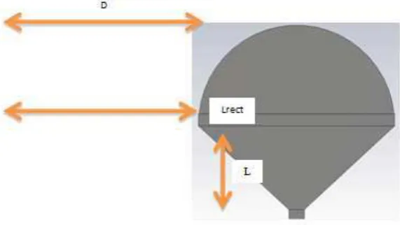
This printed planar monopole structure resembles a scoop of ice cream on a wafer cone; hence it is called as ice cream cone antenna. This antenna has microstrip feed and fabricated on FR-4 substrate with dielectric constant of 4.4, thickness of substrate is 1.6mm and tangent loss 0.019 respectively. A 50Ω microstrip line printed on a partial grounded substrate excites the antenna as shown in Figure 1. The reason of choosing the micro-strip antennat is because the micro-strip antenna has much attention due to its advantages such as UWB operating characteristic, bidirectional radiation patterns, planar structure and ease of fabrication. In order to meet the demands of a reduced antenna size, a higher dielectric constant of 4.4 can be used for this antenna but generally quite thick and lossy at UWB frequencies. As all know, patch exhibits narrowband characteristics making it challenging to enhance their bandwidth.
Fig. 1: Geometry of the printed Ice Cream Cone UWB printed monopole antenna.
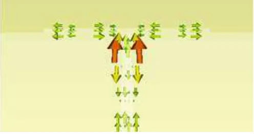
According to (Othman, M.A., I. Harrison, 2010), the feeding network is supposed to be power splitter, which divides the input power and feed them into the antenna element. However, the discontinuity of the feeding network may cause the reflection. The reflection can be reduced only if impedance matching is arrived at the branches. So, the characteristic impedance should be transformed before it is connected to the next grade of the feeding network as shown in Figure 2. The current surface flow into the feed line and antenna is shown in Figure 3 in order to understand the physics behind it.
Fig. 2: Show the geometry of the embedded feed line for proposed antenna.
The specifications of the embedded feed line are listed in Table 1.
Table 1: Optimal embedded feed line network.
Parameter Value (mm)
Lf1 14
Lf2 14
LF3 45.8
Wf1 3.2
Wf2 1.4
Fig. 3: Show the current surface flow through the embedded feed line network.
UWB Ice Cream Cone Antenna Array Design:
In order to optimize the antenna, a parameter study was carried out. By analyzing the parameter studies of the antenna, the optimum value of return loss, band width and gain will be achieved. There are several techniques or methods that have been extensively studied by many researchers, such as using reactive impedance substrate, artificial magnetic conductor modified ground plane, EBG substrate, metamaterials, and multilayer dielectric substrate. In this paper, a diameter of circular (D) have been chosen in order to improve the antenna gain as shown in Figure 4.
Fig. 4: Shows the geometry of proposed array antenna.
RESULTSANDDISCUSSION
Figure 5 shows the tuning results of D, which is the diameter of circular, and the tuning value of D starting from 19 to 22mm, respectively. Adjusting the value of D has slightly effect on the Return Loss. In the beginning, as the D = 19 mm, the maximum resonance frequency occurs at 5.3 to 5.4 GHz. As D keep increasing, the resonance starts to dive deeply at 7 GHz, near to the UWB centre frequency. At this stage the antenna impedance get close to 50 Ω, at optimum value for Return Loss by setting the value of D equal to 21 mm.
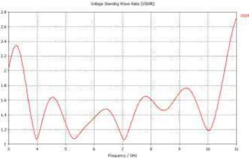
The simulated return loss (S11) curves of the Ice Cream Cone antenna (1x2) array are shown in figure 6. The measured results of the antenna element reveal a return loss lower than -10dB from 3.5 GHz to 10.6 GHz. The Voltage Standing Web Ratio (VSWR) of entire operating frequency band is illustrated in figure 7. From the figure it can clearly seen that the VSWR is less than 2, which is desired from 3.5 GHz – 10.6 GHz.
Fig. 5: Simulated Return Loss of Circular Diameter effect.
Fig. 6: Simulated Return Loss of the proposed antenna.
The simulation radiation patterns of the proposed antenna on E-plane and H-plane at resonant frequencies have been done. The proposed antenna exhibits an omni-directional pattern in H-plane and E-plane. Thus, as a conclusion the radiation pattern of the proposed antenna is almost stable in the operation band between 3.6 GHz
– 10.6 GHz.
Fig. 7: Simulated VSWR of the proposed antenna.
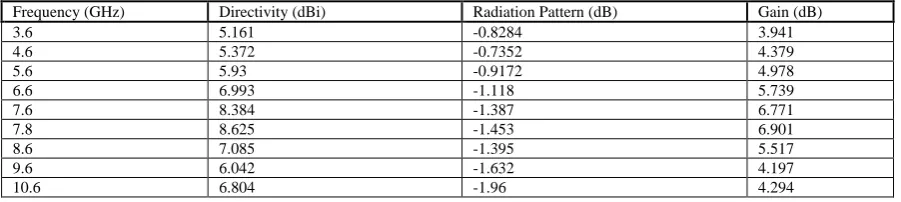
Table 3: Values of frequency, directivity, radiation pattern and gain according to the simulated proposed antenna.
Frequency (GHz) Directivity (dBi) Radiation Pattern (dB) Gain (dB)
3.6 5.161 -0.8284 3.941
This paper starts from a compact microstrip antenna element design for UWB applications. The size of 2 x 1 Ice Cream Cone antenna array is 70 x 80 mm2 with thickness is 1.6mm, after the optimization process. The Ice Cream Cone antenna array has been integrated with feeding network based on Embedded Feed Line network. The directivity and gain of proposed antenna has increase significantly over the UWB frequency range. Consequently, the Ice Cream Cone antenna array could be easily integrated and obtain the directional long-distance terrestrial broadband communications effectively. Hence, it is suitable for applications where a directional UWB antenna is required.
ACKNOWLEDGMENT
Authors would like to thanks Universiti Teknikal Malaysia Melaka for sponsoring this project. This project was funded by university short-term grant PJP/2011/FKEKK(38C)/S00935. Deep appreciations are also dedicated to anyone who directly or indirectly involved in this project.
REFERENCES
Othman, M.A., I. Harrison, 2010. “Continuous Wave (CW) sub-Terahertz (sub-THz) detection by Plasma
Wave in High Electron Mobility Transistor (HEMT),” IEEE Asia Pacific Conference on Circuits and Systems
(APCCS 2010), Kuala Lumpur, Malaysia, pp: 987-990.
Mohd Azlishah Othman, Sara Afifah Binti Abu Bakar, Mohamad Zoinol Abidin Abd. Aziz, Mohan Sinnappa, Mohd Muzafar Ismail, Hamzah Asyrani Sulaiman, Mohamad Harris Misran, Maizatul Alice Meor Said, 2013. “An Analysis of UWB Double Sided Circular Disc Bow-Tie Antenna”, IEEE International Conference on Information, Communication and Embedded System (ICICES 2013), Chennai, India, pp: 561- 565.
Mohd Azlishah Othman, Mohamad Zoinol Abidin Abd. Aziz, Mohan Sinnappa, Mohd Muzafar Ismail, Hamzah Asyrani Sulaiman, Mohamad Harris Misran, Maizatul Alice Meor Said, 2013. “An Investigation of
Drugs Detection Technique using RF Radiation Exposure in Room Temperature”, IEEE International
Conference on Information, Communication and Embedded System (ICICES 2013), Chennai, India, pp: 566 – 572.
Othman, M.A., M.M. Ismail, H.A. Sulaiman, M.H. Misran, M.A. Meor Said, 2012. “LC Matching Circuit Technique for 2.4 GHz LNA using AVAGO ATF-54143”, International Journal of Engineering Research and Applications (IJERA), 2(4): 2055-2059.
Meie Chen, Junhong Wang, 2010. “Planar UWB Antenna Array with Microstrip Feeding Network”, IEEE International Conference on Ultra-Wideband, pp: 1-3.
Min Zhang, Xin-Huai Wang, Xiao-Wei Shi, Chang-Yun Cui, Bin Wu, 2009. “A Planar Monopole Antenna
Design for UWB Applications”, 5th Asia-Pacific Conference on Environmental Electromagnetic, pp: 184-187. Kasi, B., C.K. Chakrabarty, 2012. “Ultra-Wideband antenna array design for target Detection”, Progress In Electromagnetic Research C, 25: 67-79.
Zhaohui Huang, Xian Jiang, 2010. ”Design of a Directional Ultra-Wideband Planar Antenna Array”, 9th International Symposium on Antennas Propagation and EM Theory, pp: 53-56.
Meie Chen, Junhong Wang, 2008. “Planar UWB antenna array with CPW feeding network”, Proceedings of Asia-Pacific Microwave Conference, pp: 1-4.
Kuldip N. Modha, Barrie Hayes-Gill, Ian Harrison, 2006. “A Compact, Low Loss Ice Cream Cone Ultra Wideband Antenna. The Institution of Engineering and Technology Seminar on Ultra Wideband Systems, Technologies and Applications, pp: 165-168.
Prombutr, N., P. Kirawanich, P. Akkaraekthalin, 2009. “Bandwidth Enhancement of UWB Microstrip
Habib Ullah, M., M.T. Islam, J.s. Mandeep, N. Misran, N. Nikabdullah, 2012. “A Compact wideband
Antenna on Dielectric Material Substrate for K Band”, ELEKTRONIKA IR ELEKTROTECHNIKA, 123(7): 75-78.
Bin Huang, Yingxin Xu, 2010. “Analysis and design of A Novel UWB Antenna Array”, International Conference on Microwave and Millimeter Wave Technology, pp: 313-316.
Othman, M.A., I. Harrison, 2012.“220 GHz Detection Using 0.35 µm AMS MOSFET as Sub-THz
Detector: Drain Bias Detraction”, IEEE 3rd