Voltage Source Inverter Fault Detection System using Time Frequency
Distribution
N.S. Ahmad
a, M. Mustafa
b, A.R. Abdullah
c, N.A. Abidullah
dand N. Bahari
eFaculty of Electrical Engineering, UniversitiTeknikal Malaysia Melaka (UTeM),Hang Tuah Jaya, 76100 Durian Tunggal, Melaka, Malaysia
a[email protected],b[email protected], c[email protected], d[email protected], e[email protected]
Keywords: Fault current, Monitoring,Time-frequency distribution, Spectrogram
Abstract. Open-switch and short-switch in a three-phase voltage source inverter (VSI) have a possibility to fault due to problems of switching devices.Any failure of the system in these applications may incur a cost and risk human live. Therefore, knowledgeon the fault mode behaviour of an inverter is extremely important from the standpoint of system design improvement, protection and fault detection. This paper presents detailed simulation results on condition monitoring and fault behaviour of VSI. The results obtained from the developed monitoring system allows user to identify the fault current. The developed system showed the capability in detecting the performance of VSI as well as identifying the characteristics of type of faults. This system provides a precaution and early detection of fault, thus reduces high maintenance cost and prevent critical fault from happening.
Introduction
In order to keep the overall energy efficiency high, control of generator speed is realized using power electronics. Demands on system reliability are very high and thus currently maintenance at frequent intervals is necessary. Voltage source inverter (VSI) parts are often pointed out as the weakest components of drives. Statistics generally show that the failure rates of power semiconductors, gate drives and capacitors are higher than those of electric machines even if controller failure rates are significant as well [1]. If faults occur in VSI system, an emergency stop should be executed, and appropriate maintenance should be performed. However, an emergency stop cannot be made available in special applications such as semiconductor or steel manufacturing process. Therefore, both methods are required.
Regarding VSI faults, the most common method for fault detection is by detecting the desaturation of the transistors through monitoring the collector-emitter voltage. B. Biswas et al. studied on current harmonics of an inverter-fed for induction that used fast Fourier transform (FFT) to analyze each of the frequency responses [2]. Rozailan Mamat et al. used wavelet transform (DWT) for fault detection of 3-phase VSI [3]. M. Abul Masrur et al. researched about diagnosis of open and short circuit faults in electric drive inverters for real time-applications [4]. In addition, Debaprasad Kastha et al. investigated fault modes of Voltage-Fed Inverter system. The system recognized the fault mode behaviour of inverter system.
In many applications about fault detection, the point of interest is frequency content of a signal locally in time. Time frequency distribution (TFD) is used for estimating parameter and calculates the characteristic. This paper describes about the VSI fault detection system that identifies the type of faults depending on the characteristic of parameter signal. These parameters are estimated from TFR in order to display fault detection that depends on the characteristics faults.
System Development
The monitoring system of inverter consists of three phase part which are input, interfacing and computer as shown in Fig. 1. Based on system development, phase one is a current transducer sensor (100A) used to measure current signal from inverter system. Thus, DAQ 6009 is used as data logger
Applied Mechanics and Materials Vol. 761 (2015) pp 88-92 Submitted: 19.11.2014
© (2015) Trans Tech Publications, Switzerland Accepted: 20.11.2014
doi:10.4028/www.scientific.net/AMM.761.88
from analog waveforms into digital values and transfer all data to a personal computer.The last phase is a personal computer for developing a graphical user interface (GUI) to analyse the capture signal from DAQ 6009 and then fault inverter wil be detected depending on characteristic of faults. Visual Basic 2010 is a programming system for building application and have its own benefit such as fast functionality and its programming simplicity.
Fig. 1 System development.
Experimental Work
As shown in Fig. 2, the systems of fault detection system are proposed. The performances of the system measurement are detected based on rule table characteristic parameter of signal which depends on leg of VSI. Based on experimental setup, three sensors have been used to measure three lines of inverter which arephase A, B and C. The input voltage is supplied to RL load and all measurements are collected using the system.
Fig. 2 Experimental setup for voltage source inverter (VSI).
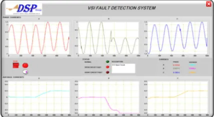
Graphical user interface (GUI) using Visual Basic 2010 is developed to capture signal for monitoring and fault detection. As shown in Fig. 3, the front panel displays the current signal patterns which is phase A, B and C. The analysis of average current was calculated and types of VSI fault detected depend on the characteristic of parameters.
Fig. 3 Front panel of voltage source inverter fault detection system.
Display
DAQ 6009 Current
Transducer
Inverter System
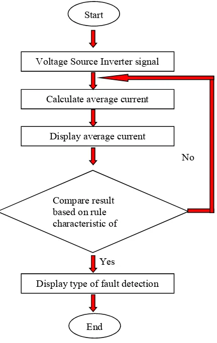
Flow chart in Fig. 4 describes about the process of VSI system has been detect the type of fault inverter. It starts with various input of current signal in terms of open and short circuit with four patterns. Then, the average current is calculated using formula in Eq.1 to 4 and value of average current is displayed at theGUI. All result can be compared based on rule characteristicof average current rule that is found out using spectrogram technique. Lastly, fault is detected and type of fault is displayed depending on calculated characteristic from the signal collected.
Fig. 4 Flow chart of the rule based characteristic.
Time Frequency Analysis Technique
Time frequency analysis technique is spectrogram that is able to represents the signal in time and frequency domain. Spectrogram is a technique suitable foranalysing non-stationary signal superior of windowed frames of a compound signal [5-7]. This technique can be defined as:
2 2
( , ) ( ) ( ) j f
x
S t f ∞h wτ τ t e− π τdτ −∞
= ∫ −
(1)
Based on TFR, the parameter has been calculated and characteristic of fault signal are identified
A. Instantaneous Average Current
0
1 ( )
,
T
Irms ave T= ∫Irms t dt
(2)
Start
Voltage Source Inverter signal
Calculate average current
Compare result based on rule characteristic of Display average current
Display type of fault detection
End Yes
No
B. Instantaneous Root Mean Square
Based on equation below, Sx(t,f) is the distribution and fmax is the maximum frequency of interest.
( )
C. Instantaneous RMS Fundamental Current
The instantaneous RMS fundamental current is as the RMS current at power system frequency [8-10] can be calculated as
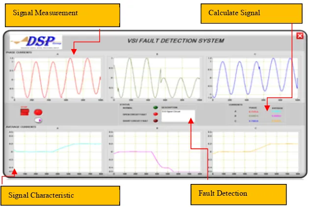
The development of graphical user interface (GUI) of the VSI fault detection system is shown in Fig. 5. The GUI is capable of measuring the average current of each leg inverter and display characteristic of its respective signal. The system is also able to detect type of inverter faults such as open circuit upper switch, open circuit lower switch, short circuit upper switch and short circuit lower switch[2].
Fig. 5 Voltage source inverter fault detection system (VSIFa).
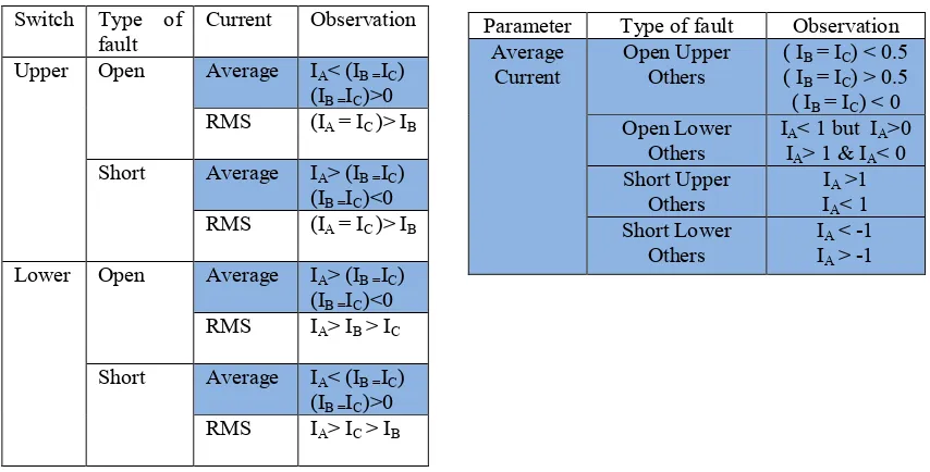
The characteristic types of fault were calculated using TFD and all resultsaresummarizedin Table 1. From the analysis on characteristic of fault, the average and RMS current was observed for Voltage Source Inverter Fault Detection System (VSIFa). Then the VSIFa refers to Table 1 as a rule for detecting fault and monitor signal characteristic, calculate signal parameter and detecting type of faults. Besides that, this system isable to monitor three phases of current which are phase A, phase B and phase C, for all type of faults [11].
Signal Measurement
Signal Characteristic Fault Detection Calculate Signal
Table 1 Characteristic type of fault based on time frequency distribution.
Conclusion
In this paper, the development of VSI switches fault system by using TFDs. The system performs parameter such as average current and RMS current. Based on the monitoring testing, the system capable for detected open and short-circuit switches fault in switching devices. From the results achieved show that this inverter system can fit in substantial safety critical and industrial application where fault prime vital.
References
[1] N.H. Kim, M.H. Kim, H.A. Toliyat, S.H. Lee, C.H. Choi, W.S. Baik, "Rotor Fault Detection System for the Inverter Driven Induction Motor using Current Signals". 7th Internatonal Conference on Power Electronics, pp. 724-728, Oct 2009.
[2] B. Lu, S.K. Sharma. A literature review of IGBT fault diagnostic and protection methods for power inverters. IEEE Trans. Ind. Appl. 45 (2009) 1770-1777.
[3] M.R. Mamat, M. Rizon, M.S. Khanniche, Fault detection of 3-phase VSI using wavelet-fuzzy algorithm. Am. J. Appl. Sci. 3(1) (2006) 1642-1648.
[4] M. Abul Masrur, Z.H. Chen, Y.L. Murphey, Intelligent diagnosis of open and short circuit faults in electric drive inverters for real-time applications. IET Power Electronics. 3 (2010) 279-291. [5] A.R. Abdullah, N.S. Ahmad, N. Bahari, M. Manap, A. Jidin, M.H. Jopri, "Short-Circuit Switches
Fault Analysis of Voltage Source Inverter using Spectrogram" International Conference on Electrical Machines and Systems (ICEMS), pp. 1808-1813, Oct 2013.
[6] A.R. Abdullah, A.Z. Sha'ameri, "Power quality analysis using linear time-frequency distribution" 2nd IEEE International Conference on Power and Energy (PECon), pp. 313-317, Dec 2008. [7] A. Kusko, M. Thompson, Power Quality in Electrical Systems. McGraw Hill, 2007.
[8] A.R. Abdullah, N.S. Ahmad, E.F. Shairi, A. Jidin, "Open Switch Faults Analysis in Voltage Source Inverter using Spectrogram", IEEE Power Engineering and Optimization Conference (PEOCO), pp. 438-443, Jun 2013.
[9] A.R. Abdullah, A.Z. Sha'ameri, N.M. Saad," Power Quality Analysis using Spectrogram and Gabor Transformation". Asia-Pacific Conference on Applied Electromagnetics Proceedings (APACE), pp. 4-6, Dec 2007.
[10] N.S. Ahmad , A.R. Abullah, N. Bahari, Open and short circuit switches fault detection of voltage source inverter using spectrogram. J. Int. Conf. Electr. Mach. Syst. 3 (2014) 190-199.
Switch Type of
fault Current Observation Upper Open Average IA< (IB =IC)
Parameter Type of fault Observation Average