I hereby, declare I had read through this thesis entitled “Effect of Air Velocity on Solid
Waste Combustion” and I agree that this thesis had fulfilled the quality and scopes that
worth it to award Degree of Mechanical Engineering (Structure-Material).
Signature
: ………
Supervisor’s Name
: ………
i
EFFECT OF
AIR VELOCITY AND EQUIVALENCE RATIO ON
SOLID WASTE COMBUSTION
ADAM WONG YUNG SENG
This report is submitted to
Faculty of Mechanical Engineering
University Teknikal Malaysia Melaka
In Partial Fulfillment for Bachelor of Mechanical Engineering
(Structure & Material)
Faculty of Mechanical Engineering
University Teknikal Malaysia Melaka
ii
"I hereby declared that this thesis titled
'Effect of Air Velocity and Equivalence Ratio on Solid Waste Combustion ' is the result
of my own effort except as clearly stated in references the source of reference".
Signature : ____________________
iii
Special dedication to my late and loving father, Andrew Wong Kiong Ming who
passed away last year. He will always be remembered. Dedication as well to my mother
whom, also had taken good care of me. Not forgetting as well both my brothers, who
had been with me all this while.
iv
ACKNOWLEDGEMENTS
I would like to give my first credit to all my faculty staffs at Universiti
Teknikal Malaysia Melaka (UTeM) that involved in my PSM research. Among them is
Puan Ernie as my PSM supervisor. She had provided a lot of assistance and guidance
from the beginning, after I had chosen her topic as my PSM research. She always ready
to help despite of her busy work schedule. She frequently keeps track with my work
progress and provide useful advices and guidance.
v
ABSTRACT
vi
ABSTRAK
vii
TABLE OF CONTENTS
PAGE NO
.
DECLARATION
ii
DEDICATION
iii
ACKNOWLEDGEMENT
iv
ABSTRACT
v
TABLE OF CONTENTS
vii
LIST OF TABLES
x
LIST OF FIGURES
xii
LIST OF SYMBOLS
xv
LIST OF APPENDICES
xvi
CHAPTER I
INTRODUCTION
1
1.1
Introduction
3
1.2
Objective
3
1.3
Work Scopes
3
1.4
Problem Statements
4
viii
CHAPTER II LITERATURE REVIEW
5
2.1 Introduction
5
2.1.1 History of Gasification
7
2.2 Stoichimetric Combustion
10
2.3 Fixed Bed Gasifier System
11
2.4 Updraft Gasifier 14
2.4.1 Operating Systems
15
2.4.2 Process Zones 15
2.5 Application of Updraft Gasifier
17
2.6 Air Velocity 19
2.7 Equivalence Ratio 22
CHAPTER III
METHODOLOGY
26
3.1
Gasifier Of UTeM
26
3.2
Preparation of Variation of
28
Air Velocity
3.2.1 Producing Different Values of
Air Velocity
28
3.2.2 Measuring of the Air Velocity
31
3.3
Temperature Measurement
32
3.3.1 Thermocouple
32
3.3.2 Data Logger
33
3.4
Solid Waste Properties
34
3.5
Input Properties
35
3.5.1 Determination of Equivalence Ratio 36
3.6
Flame Temperature
39
ix
CHAPTER IV
EXPERIMENTAL RESULT AND DISCUSSION
41
4.1
Introduction
41
4.2
Temperature Distribution in Variation of
42
Air Velocity
4.2.1 Temperature Distribution of Zero
Air Velocity
43
4.2.2 Temperature Distribution of 3 m/s
46
4.2.3 Temperature Distribution of 4 m/s
49
4.2.4 Temperature Distribution of 5 m/s
52
4.2.5 Temperature Distribution of 6 m/s
55
4.3
Maximum Adiabatic Flame temperature
58
4.3.1 Maximum Adiabtic Flame Temperature
for all thermocouples
58
4.3.2 Adiabatic Flame temperature of all
thermocouple one
60
4.3.2 Adiabatic Flame temperature of all
thermocouple six
62
4.4
Performance Analysis of UTEM’s gasifier
64
4.5
Evaluation of Understanding/ Finding
66
CHAPTER II CONCLUSION
68
5.1 Introduction
68
5.2 Conclusion
68
5.3 Recommendation
70
REFERENCES
71
APPENDICES
74
x
LIST OF TABLES
NO. TITLE.
PAGE NO.
2.1 Types of Fixed Bed-Gasifier
13
2.2 Generic Formulas
25
3.1 Specifications of Air Blower
29
3.2 Air Velocities Obtained
30
3.3 Specifications of Data Logger
33
3.4 Feedstock Input Properties
34
3.5 Input parameters used in experimental work
35
3.6 Parameters used in determination of actual air over fuel ratio
37
3.7 Diameter of blower outlet for air velocity conducted
38
4.1 Equivalence ratio and maximum adiabatic temperature for zero
air velocity
43
xi
4.3 Equivalence ratio and maximum adiabatic temperature for 4 m/s
49
4.4 Equivalence ratio and maximum adiabatic temperature for 5 m/s
52
4.5 Equivalence ratio and maximum adiabatic temperature for 6 m/s
55
xii
LIST OF FIGURES
NO. TITLE.
PAGE NO.
2.1 Pyrolysis of Carboneous fuels char
6
2.2 Gasification of Char
6
2.3 Integrated gasification Combined Cycle, or IGCC
7
2.4 Wood Waste
8
2.5 Burning Log in Campfire
9
2.6 Fixed Bed Gasifier
11
2.7 Updraft Gasifier
14
2.8 Updraft Gasifier For Corn Drying
17
2.9 An Updraft Gasifier Plant
18
2.10 The Effect of Air Addition on Condensable Hydrocarbon
20
xiii
2.12 The Effect of Air Addition on Gasification Efficiency
21
2.13 Diagram of Equivalence Ratio and Air Fuel
25
3.1 Schematic Diagram of UteM’s Gasifier
26
3.2 Actual View of UTeM’s Gasifier
27
3.3 Working Combination of Air Blower and Pipe
28
3.4 Opened Opening
29
3.5 Closed Opening
29
3.6 Connection of Pipes
30
3.7 Anemometer
31
3.8 Thermometer Type K
32
3.9 Data Logger
33
3.10 Construction Wood
34
3.11 Whole Setting of Equipment
40
3.12 Screen View of the Data Logger Software
40
4.1 Location and listing numbers of the thermocouples in gasifier
42
xiv
4.3 Temperature distribution of 3 m/s
47
4.4 Temperature distribution of 4 m/s
50
4.5 Temperature distribution of 5 m/s
53
4.6 Temperature distribution of 6 m/s
56
4.7 Maximum Adiabatic Temperature for all Thermocouples
59
4.8 Graph for all T1 combined
61
xv
LIST OF SYMBOLS
d
=
Diameter
A
=
Area
v
=
Velocity
Q
=
Volumetric flow rate
ρ
=
Density
xvi
LIST OF APPENDICES
NO. TITLE.
PAGE NO.
A Carry Out PSM Flow Chart
75
B Grant Chart for PSM 1
76
C Grant Chart for PSM 2
77
D Technical Drawing of the Gasifier
78
E Draft Drawing of the Gasifier
79
F Calculation of Equivalence Ratio
80
1
CHAPTER 1
INTRODUCTION
1.1
Solid Waste
Despite of the progression of our humankind civilization, we have
produced many wastes. This waste may in the form of solid, liquid and gas as well
as either biodegradable or non biodegradable. Solid waste can be divided to
several types namely garbage, rubbish, ashes, industrial wastes, mining wastes,
agricultural wastes and may more others. Due to different types of solid waste,
different methods are invented and used. Among the methods are automotive
shredder residue (ASR), gasification, in-vessel composting, pyrolysis and so on.
2
According to Lefcort, M.D, (1995), gasification is a special case of
pyrolysis. It involves the process of converting carbonaceous materials into
carbon dioxide and hydrogen by reacting the raw material at high temperature
with controlled oxygen and steam. Gasification is a very efficient method for
extracting energy from many different types of organic materials. In this research,
the work will emphasize on the gasification of wood waste. The resources of
wood waste include construction fields, furniture industries, paper industries, old
furniture and so on. These solid wood wastes are usually left to decompose
naturally in the dumpsites. However, in case the solid waste is burnt with the right
method, it has the potential to generate electricity. This is a beneficial situation as
it not only reduce the solid waste but also as an alternative for energy source.
The equipment that used to convert the solid fuel is solid waste gasifier.
The solid fuels such as wood waste, saw dust briquettes and agro-residues are
converted into a gaseous fuel through a thermo-chemical process. This resultant
gas is very useful to produce heat which in turn applied in power generation
applications. There are three type of gasifiers namely downdraft, updraft and
crossdraft, which is classified according to the way air or oxygen is introduced
into it.
3
1.2
Objective
1.
To determine the optimum operating parameter of a gasifier for
different air velocity.
2.
To determine the gasifier mode operation which is either in
pyrolysis, gasification or combustion.
1.3
Work Scopes
1.
To run experimental work under various air velocity.
2.
To determine the gasifier mode operation from equivalence ratio
value.
3.
To determine the axial and outlet flame temperature distribution in
the gasifier.
4
1.4
Problems Statement
No extensive work on the gasifier through experimental or simulation work.
Hence, this study is done to analyze the performance of the gasifier with various
air velocities to get the suitable axial flame temperature.
1.5
Significant of Study
A laboratory scale of the updraft gasifier is used in this research. The updraft
5
CHAPTER 2
LITERATURE REVIEW
2.1
Introduction
Christine and Gable, S. (2008) in http://alternativefuels.about.com
described that the gasification is an exothermic reaction between a high carbon
fuel and a carefully controlled and limited supply of oxidizer, together with heat,
pressure, and steam to convert materials directly into a gas composed primarily of
carbon monoxide and hydrogen. Gasification is also identified as a type of
pyrolysis. However, the pyrolysis involved the destructive decomposition of wood
waste into charcoal, oils, tars and gas when the pyrolysis occurred at below 593
°C or 1,100°F. However in gasification, there are no formation of oil, tar and
charcoal byproducts as all the solid wood waste is converted to the burnable gas
of mainly carbon monoxide, hydrogen and methane.
Both the process of the pyrolysis and gasification is shown in the Figure
2.1 and Figure 2.2 below. In Figure 2.1, the pyrolysis occurred without sufficient
air and yields products of hydrogen (H
2
), tars and methane (CH
4). As for the
6
introduced and able to convert all char into products of
hydrogen (H₂),
carbon oxide (CO) and carbon dioxide (CO
2
).
(Source: http://en.wikipedia.org/wiki/Gasification)
Mainly the raw materials used in gasification are coal, petroleum-based
materials, and organic materials. The raw material or feedstock can be prepared
and fed, either in dry or slurried form, into a sealed reactor chamber called a
gasifier. In the gasifier, the feedstock is subjected to high heat, pressure, and
controlled amount of oxygen. The environment in the gasifier is either
oxygen-rich or oxygen-starved environment. However, oxygen is not required in mostly
commercial gasification technologies.
Gasification produces three primary products, namely hydrocarbon gases
(syngas), hydrocarbon liquids (oils) and char (carbon black and ash). The syngas
is primarily carbon monoxide and hydrogen (
≥
85 percent) and smaller quantities
of carbon dioxide and methane. Both syngas and oil has the potential in
generation of electricity and other wide usages.
Figure 2.1: Pyrolysis of
carbonaceous fuels char
7
2.1.1
History of gasification
The history of gasification dated back to mid-1800’s and had undergo a
long history of development. It is initially used to produce ‘town gas’ from coal
for heating, cooking and lightning purpose. This ‘town gas’ is later substituted by
natural gas after the founding of the gas fields. The break-out of World War II had
caused fuel shortages in Europe. This leads the Europeans to return to
gasification-powered energy to power their motor vehicles. Thus, wood gas
generators named Gasogene or Gazogene is introduced. After the war, demand for
liquid fuels remained and the German engineers made a successful production of
synthetic liquid fuel from gasified coal.
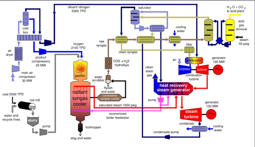
[image:24.595.114.525.484.721.2]In the 1970’s the U.S. government launched a large industrial scale
gasification projects due to the Arab Oil Embargo and the “energy crisis”. From
this development came the first Integrated Gasification Combined Cycle (IGCC)
electric generating plant. Presently, several IGCC power plants are operating
throughout the world. And crude oil price spikes and geopolitical instabilities in
major oil-producing countries have generated serious interest in using gasification
for GTL (Gas To Liquid) synthetic fuel processes.
Figure 2.3: Integrated Gasification Combined Cycle, or
IGCC