UNIVERSITI TEKNIKAL MALAYSIA MELAKA
EXTENDED HYBRID ELECTRIC MOTORCYCLE MOTOR
MOUNT DESIGN, ANALYSIS AND INSTALLATION
This report submitted in accordance with requirement of the Universiti Teknikal Malaysia Melaka (UTeM) for the Bachelor Degree of Mechanical Engineering
Technology (Automotive) (Hons.)
by
SYLVESTER SULIP B071210002 931106-12-5211
UNIVERSITI TEKNIKAL MALAYSIA MELAKA
BORANG PENGESAHAN STATUS LAPORAN PROJEK SARJANA MUDA
TAJUK:
Extended hybrid electric motorcycle motor mount design, analysis
and installation.
SESI PENGAJIAN: 2015/2016 SEMESTER 1
Saya SYLVESTER SULIP
mengaku membenarkan Laporan PSM ini disimpan di Perpustakaan Universiti Teknikal Malaysia Melaka (UTeM) dengan syarat-syarat kegunaan seperti berikut:
1. Laporan PSM adalah hak milik Universiti Teknikal Malaysia Melaka dan penulis. 2. Perpustakaan Universiti Teknikal Malaysia Melaka dibenarkan membuat salinan
untuk tujuan pengajian sahaja dengan izin penulis.
3. Perpustakaan dibenarkan membuat salinan laporan PSM ini sebagai bahan pertukaran antara institusi pengajian tinggi.
4. **Sila tandakan ( )
SULIT
TERHAD
TIDAK TERHAD
(Mengandungi maklumat yang berdarjah keselamatan atau kepentingan Malaysia sebagaimana yang termaktub dalam AKTA RAHSIA RASMI 1972)
(Mengandungi maklumat TERHAD yang telah ditentukan oleh organisasi/badan di mana penyelidikan dijalankan)
Alamat Tetap:
FAKULTI TEKNOLOGI KEJURUTERAAN
PENGKELASAN LAPORAN PSM SEBAGAI SULIT/TERHAD LAPORAN PROJEK SARJANA MUDA TEKNOLOGI KEJURUTERAAN MEKANIKAL (TEKNOLOGI AUTOMOTIF): SYLVESTER SULIP
Sukacita dimaklumkan bahawa Laporan PSM yang tersebut di atas bertajuk
“Extended Hybrid Electric Motorcycle Motor Mount Design, Analysis and
Anstallation” mohon dikelaskan sebagai *SULIT / TERHAD untuk tempoh
LIMA (5) tahun dari tarikh surat ini.
2. Hal ini adalah kerana IANYA MERUPAKAN PROJEK YANG DITAJA OLEH SYARIKAT LUAR DAN HASIL KAJIANNYA ADALAH SULIT.
Sekian dimaklumkan. Terima kasih.
Yang benar,
________________
Tandatangan dan Cop Penyelia
* Potong yang tidak berkenaan
NOTA: BORANG INI HANYA DIISI JIKA DIKLASIFIKASIKAN SEBAGAI
SULIT DAN TERHAD. JIKA LAPORAN DIKELASKAN SEBAGAI TIDAK
TERHAD, MAKA BORANG INI TIDAK PERLU DISERTAKAN DALAM
DECLARATION
I hereby, declared this report entitled “Extended hybrid electric motorcycle motor mount design, analysis and installation” is the results of my own research except as cited in references.
Signature : ... Author’s Name : SYLVESTER SULIP
APPROVAL
This report is submitted to the Faculty of Engineering Technology of UTeM as a partial fulfilment of the requirements for the Degree of Bachelor of Mechanical Engineering Technology (Automotive)(Hons.). The member of supervisory is as follow:
i
ABSTRAK
ii
ABSTRACT
iii
DEDICATION
I dedicate my dissertation to my family and many friends. A special feeling of gratitude to my be loving parents whose give me endless support throughout my studies and to my family whose never left me alone and are very important to me.
iv
ACKNOWLEDGEMENT
Firstly, most thanks to God for giving me the opportunity to complete this final year report with a success after I went through a lot of obstacles with patience. I would also like to thank my parents for encouraging me throughout all the heavy situations I am facing and keep supporting on my financial. I would not be in this university and not be able do my degree project without their permission and blessing.
Not to forget, I would like to thank my former supervisor, Mr. Ir. Mazlan bin Ahmad Mansor and my current supervisor, Mr. Muhammed Noor bin Hashim for guiding me in completing this project and report. They has taught me a lot of useful things and knowledge not only in theoretical but also practical. Furthermore, thanks to all lecturers and technicians that has guided me to get a good knowledge and experiences either in the class or in the lab session.
Besides, I would also like to thank all of my fellow friends including my friends under the same supervisors, Muhammad Ramdan bin Mat Ali and Mohamad Shahril Ikhmal bin Samsaimon for sharing their opinions regarding this project report.
v
List Of Abbreviations, Symbols And Nomenclatures XI
CHAPTER 1 1
INTRODUCTION 1
1.1PROJECT BACKGROUND 1
1.2 Problem Statement 1
1.3 Objectives 2
1.4 Scope Of Project 2
1.5 Methodology Of Project 3
1.6 Thesis Organization 3
CHAPTER 2 5
LITERATURE REVIEW 5
2.1 Introduction 5
2.2 Development of Rigs for Testing 5
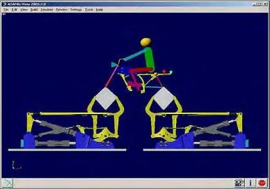
Figure 2.1. Example of multi-body simulation using ADAMS® simulation
software 7
2.2.1 Automotive Component Test Rigs 7
vi
2.3 Research Project On Swingarm 11
2.3.1 Swingarm Test Rigs 12
2.3.2 Leyni durability test 12
2.4 Swingarm development 13
2.5 Motivation to Develop a New Swingarm 19
2.6 Significance of Research 20
2.7 Project Objectives 20
2.7.1 Phase 1- Design of Test Rig 21
2.7.2 Phase 2- Evaluation of swingarm Performance 21
2.7.3 Phase 3- Evaluation of Results 21
2.8 Chapter Summary 22
CHAPTER 3 23
METHODOLOGY 23
3.1 Overview 23
3.2 Determine the problem statement, objective and scope of study 26
3.3 Project schedule 26
3.4 Literature survey 26
3.4.1 Research and site visit 26
3.4.2 Reference materials observation 27
3.5 Engineering design process 27
3.5.1 Preliminary Design 27
3.5.2 Drawing design 29
3.5.3 Material selection 30
3.5.4 Design sample result 30
3.6 Tools 31
3.7 Selection of machine and equipment 32
3.7.1 Toolbox spanner 32
3.7.2 Welding machine 33
3.8 CAD Software 36
3.9 Parametric design 37
3.9.1 Design for the environment 37
vii
3.10.1 Part design 38
3.10.2 Assembly of swingarm 43
3.11 General Idea Using FEA 46
3.12 Modelling of swingarm 46
3.13 Material data 48
3.14 Computational setup 49
3.15 Fabricate 51
CHAPTER 4 53
RESULT & DISCUSSION 53
4.1 Finite element result 53
4.1.1 Meshing 53
4.1.2 CATIA analysis result 54
4.2 Fabricate result 65
CHAPTER 5 67
CONCLUSION & FUTURE WORK 67
5.1 Conclusion 67
5.2 Future work 68
viii
LIST OF TABLE
3.1 Gantt chart of the project 25
3.2 Material properties of steel 48
4.1 Mesh 54
4.2 Element type 54
4.3 Element quality 54
4.4 Materials data 54
4.5 Structure computation 55
4.6 Minimum and maximum pivot 57
4.7 Minimum pivot 58
4.8 Translational pivot distribution 58
4.9 Equilibrium 58
ix
LIST OF FIGURE
Figure 2.1. Example of multi-body simulation using ADAMS® simulation software.
Kharul R et al. (2010) 7
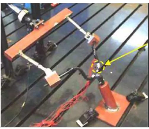
Figure 2.2. Durability test rig for motorcycle handlebars. K. Lin et al. (2005). 8 Figure 2.3. Durability test rig for suspension system 9 Figure 2.4. Loads acting on the swingarm during cornering assuming thin wheels. E.
Armentani et al. (2007). 14
Figure 2.5. Loads acting on the swingarm during cornering assuming thickwheels. E.
Armentani et al. (2007). 14
Figure 2.6. Lateral loading of the double-sided aluminium swingarm using spacer and spindle to simulate real loading conditions. E. Armentani et al. (2007). 15 Figure 2.7. Torque-angle curves for three swingarms. G. Risitano et al. (2012). 17
Figure 3.1. Flow chart of project. 24
Figure 3.2. The initial sketches for the swingarm 28
Figure 3.3. Swingarm design 29
Figure 3.4. Steel material 30
Figure 3.5. Sample result 31
Figure 3.6. Toolbox spanner 33
Figure 3.7: The well-dressed (safe) welder attires that need to be followed. 35 Figure 3.8: Equipment needed to perform welding using MIG machine. 35
Figure 3.9: Logo of CATIA V5 used. 36
Figure 3.10.1: Left swingarm 38
Figure 3.10.2: Right swingarm 39
Figure 3.10.3: Screw holder absorber 40
Figure 3.10.4: Holder 40
Figure 3.10.5: Base holder 41
Figure 3.10.6: Cylinder 41
Figure 3.10.7: Chock 42
Figure 3.10.8: Brake clamp holder 42
Figure 3.10.9: Body holder 43
x
Figure 3.10.11: Isometric view 45
Figure 3.12.1: brake clamp holder 47
Figure 3.12.2: Swingarm 48
Figure 3.14.1: Clamp area 49
Figure 3.14.2: Force applied 50
Figure 3.15.1: Bending process 51
Figure 3.15.2: Cutting process 52
Figure 3.15.3: MIG welding process 52
Figure 4.1: Boundary condition 55
Figure 4.2: Deformed mesh 59
Figure 4.3: Von mises stress 59
Figure 4.4: Translational displacement 60
Figure 4.5: Stress principal tensor 60
Figure 4.6: Estimated local error 61
Figure 4.7: Von mises stress value 64
Figure 4.8: Displacement value 65
xi
LIST OF ABBREVIATIONS, SYMBOLS AND
NOMENCLATURE
BST - Black Stone Tek
CAD - Computer Aided Design CAE - Computer Aided Engineering CAM - Computer Aided Manufacturing
CATIA - Computer Aided Three-dimensional Interactive Application EDS - Electro Dynamic Shaker
FE - Finite Element
1
CHAPTER 1
INTRODUCTION
1.1 Project background
Nowadays, there are a lot of motorcycle swing arm designs available in the market with a variety purposes. The fast growing technologies happening in this era, all the motorcycle swing arm become more advance in design. Meanwhile, the hardness of the swing arm is important in order to support the weight of the bike or motorcycle.
By developing this mounting bracket for Hybrid Electric Motor (HEM), the swing arm design with 3D and 2D using software CATIA. Indeed, the analysis also using this software to analyse the force acting to swing arm. After that, fabricate the swing arm and install to motorcycle to run the testing.
1.2 Problem statement
2
front wheel is turned during the steering process. This is usually the angle with respect to the vertical of the steering head of the frame. In design of the swing arm, holder calliper of disc brake also need to design the suitable position to hold the calliper disc brake for rear tyre.
1.3Objectives
The objective of this project are as following:
i. To design the bracket for electric hub on a motorcycle swing arm. ii. To perform the strength analysis.
iii. To fabricate the swingarm.
1.4 Scope of project
3 1.5 Methodology of project
The methodology in order to do this project is as follows.
i. Research some related developments, studies and examples of current project. ii. Design and fabricate of detail structure that need to be built.
iii. Development of the project. iv. Testing the performance.
1.6 Thesis organization
This report contains five chapters. Chapter one describes about the introduction of the project, the Design, analysis, Fabricate, install and testing of mounting bracket swing arm for Hybrid Electric Motor (HEM). The problem statement of the project, the objectives of the project, a purpose that describes the motives to develop the project, the scope of the projects, and organization of the report are stated and explained in chapter one.
Chapter two is about the literature review about the field of study regarding the project. This chapter reviews on theoretical information, results of researches related to the field of this project, and applications needed to be applied on design swing arm motorcycle. All the information gathered were discussed and explained.
4
Chapter four explains the results and discussion of this project. After finished constructing the Swing Arm, testing procedure is done to evaluate the work. The data from the analysis will determine the effectiveness and efficiency of Swing Arm
5
CHAPTER 2
LITERATURE REVIEW
2.1 Introduction
The motorcycle swing arm is a key component of the rear suspension of a motorcycle. It connects the rear wheel of the motorcycle to the main chassis and it regulates the rear wheel-road interactions via the spring and shock absorber. Two basic designs exist, namely the single-sided and double-sided swing arms. The single-sided swing arm has the benefit of allowing for easier removal of the rear wheel during racing. The disadvantage is that due to the asymmetry, a twisting moment acts in the arm which does not exist in a double-sided swing arm.
2.2 Development of Rigs for Testing
Nowadays, there are highly competitive for automotive world, automotive manufacturers are focussing their efforts on shortening product development cycle without compromising performance and reliability Kharul R et al. (2005). This means it reduces test time by identifying failure modes early in the design process and avoid past design by optimizing their components necessary for life Singanamalli A et al. (2004). Research also indicates that a greater level of stability can be achieved by properly optimizing the design parameters without compromising ride comfort requirements Mangaraju KV et al. (2004).
6
the development process before it is available and also allows data to be acquired to help by providing a test trial Kharul R et al. (2010). Virtual model of the best in conveying an understanding of system behavior, interactions and sensitivity, while good physical exam to determine the absolute level of performance and the response of complex systems P. Wilkinson. (2007). It is very difficult to predict the future of motorcycle history loading. One solution is to fit strain gauges and transducers ridden other bikes on the road-track a variety of conditions. With adequate test, one can build a picture of the normal engine load cycles over the life expectation. The second solution is to build a test rig that can simulate road conditions Piazza SD. (2008). The first one is not an option because of BST has no motorcycle for testing purposes, but they are willing to invest in test rigs.
Physical tests must be conducted to validate the design and determine the accuracy or virtual simulation test. Virtual testing cannot replace physical testing Kharul R et al. (2010). Physical testing can be performed on the test platform to validate the simulation if it reproduces realistic failure as it happens on the field Balakrishnan S. (2012). A similar approach is required in this study to develop a test platform that resembles a proper road conditions to test the durability and performance of the swingarms.
7
Figure 2.1. Example of multi-body simulation using ADAMS® simulation software. Kharul R et al. (2010)
From this discussion on the test rig, it is clear that for successful design and testing of automotive components, there is a need to incorporate a virtual (FEA) and experimental methods.
2.2.1 Automotive Component Test Rigs
8
good physical exam to determine the absolute level of performance and the response of complex systems P. Wilkinson. (2007).
Durability test has been widely used in the design of automotive components. Servo hydraulic platform (used for durability testing) is one of the main experimental methods used in the automotive design K. Dressler et al. (2009). Endurance test rig was built to test the fatigue life of the motorcycle handlebars shown in Figure 2.2 K. Lin. (2005), the suspension of the vehicle shown in Figure 2.3 and the motorcycle frame R. Ide et al. (2009), to name a few. During the test, the results are usually obtained by measuring the strain in the component and then calculate the corresponding stresses.