ANALOGUE ELECTRONIC TRAINER (BJT)
AINUN NAZIROH BINTI AHMAD SUKRI
ANALOGUE ELECTRONIC TRAINER (BJT)
AINUN NAZIROH BINTI AHMAD SUKRI
This report is submitted in partial fulfillment of the requirement for the award of Bachelor of Electronic Engineering (Industrial Electronics)
Faculty of Electronic and Computer Engineering Universiti Teknikal Malaysia Melaka (UTeM)
v
ACKNOWLEDGMENT
Bismillahirahmanirrahim. In the name of Allah that most gracious and most merciful.
Praise for Allah SWT for giving me the chance to live until today and experience what I had thus
far. I’m always thankful for where I am today, for the chance to be given education and better
luck from the misunfortunates. I also believe in His Qada’ and Qadar which brought me to be a
student at Universiti Teknikal Malaysia Melaka and to do my final year project this semester.
First of all I would like to thank my parents for their endless love and support since I was
born. They’re the ones who always drive me to excel and challenge myself to be better than I
was before, in education and life. There’s no way I can repay their deeds and the only way I can
somehow is to be successful as a daughter, a scholar, a Muslim and a person.
In addition to that I would like to express my appreciation to my supervisor, Mr. Farid
Arafat Bin Azidin for these 28 weeks for all those times and ideas helping me to finish the
project. In other words, I’m very thankful to have Mr Farid as my supervisor.
ABSTRACT
vii
ABSTRAK
TABLE OF CONTENTS
TABLE OF CONTENTS viii
LIST OF FIGURES xi
LIST OF TABLES xiii
LIST OF ABBREVIATIONS xiv
ix
II PROJECT BACKGROUND
2.1Theory of BJT configuration circuit 2.1.1 Fixed bias configuration 2.1.2 Emitter bias
2.1.3 Voltage divider bias 2.1.4 Collector feedback 2.1.5 Cascaded configurations 2.2Trainer available in market 2.3Theory on Component
2.3.1 Component Adapter 2.4Proteus software
9
III PROJECT METHODOLOGY
3.1Discussions With Supervisor 3.2Research
3.3Survey and observation 3.4Create Lab Sheet sample 3.5Simulation
3.6Designing
3.6.1 PCB board of BJT circuit
3.6.2 Base trainer and component adapter 3.7Prototype developing
3.7.1 Designing
3.7.9 Board testing 34
IV RESULTS/ ANALYSIS
4.1 Prototype
4.2 Multisim Simulations 4.2.1 DC analysis 4.2.2 AC analysis
4.3 Trainer experimental result 4.4 Analysis
V CONCLUSIONS AND RECOMMENDATIONS
xi
LIST OF FIGURES
FIGURE TITLE PAGE
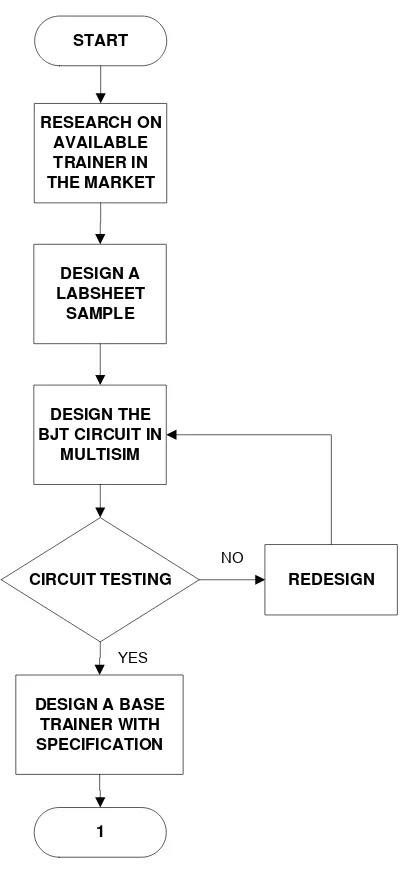
1.1 Progression on PSM I 5
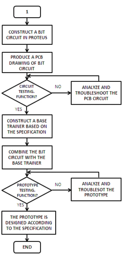
1.2 Progression on PSM II 6
2.1 Fixed Bias 10
2.2 Collector loop of fixed bias 11
2.3 Emitter Bias 12
2.4 Collector loop of emitter bias 13
2.5 Voltage divider Bias 14
2.6 Collector feedback path 16
2.7 Collector loop of feedback bias 17
2.8 Cascaded Circuit 18
2.9 Class ‘A’ amplifier trainer 19
2.10 BJT Amplifier Trainer 20
2.11 BJT Trainer 21
2.12 Component Adapter 23
2.13 Banana Plug 24
2.14 Proteus welcome page 24
3.3 The side view of base trainer 29 3.4 Component adapter in Proteus software 29
3.5 Photo board 30
3.6 Correct designing 31
3.7 Insert PCB into etching machine 32
3.8 Remove the film on the track 33
3.9 After the film removed 33
4.1 PCB board 35
4.2 Base Trainer With PCB Board 36
4.3 Component Adapter for BJT, Capacitor and Resistor. 36
4.4 Voltage Drop 37
4.5 Current Collector , Ic 38
4.6 Waveform of Vout from multisim 40
4.7 Input voltage ±15 of 10% tolerance 42
4.8 Voltage drops at VR1 42
4.9 Voltage drops at VRC 43
4.10 Voltage drops at VR2 43
4.11 Voltage drop at VRE 43
4.12 Current at collector, IC. 44
xiii
LIST OF TABLES
NO TITLE PAGE
1 Traco model with description 22
2 Simulation results of DC analysis 38
3 Calculated results of DC analysis 39
4 Simulation Result of Vout 40
5 Measured Values of DC analysis 42
6 Measured Results of Vout 44
LIST OF ABBREVIATIONS
AC – Alternating Current
ARES - Advanced Routing and Editing Software BJT - Bipolar Junction Transistor
CNC – Computerized Numerical Control DC – Direct Current
FET - Field Effect Transistor
GND - ground
ISIS - Intelligent Schematic Input System OP-AMP - Operational Amplifier
PCB – Printed Circuit Board UV – Ultra Violet
xv
LIST OF APPENDIX
APPENDIX TITLE PAGE
A Gantt Chart 53
B Example Labsheet 54
C Datasheet Traco Power 61
CHAPTER I
INTRODUCTION
This chapter will give an overview of the project such as project overview, project objective, project scope, project methodology and the structure of this project report. This chapter will explain briefly about the work from the beginning until the project is implemented.
1.1Project Overview
The trainer is a training kit that normally used in the laboratory either at school, college or university. Most of the students assemble their experiment by using certain a trainer such as a common emitter trainer, FET trainer and so on. Unfortunately, each of the trainers is fixed with one design and all the components are mounted in.
2
This project utilizes a bipolar junction transistor (BJT) circuit configuration on DC analysis and Ac analysis. A bipolar junction transistor (BJT) consists of two back-to-back p-n junctions and the contacts are made in all three regions with the two outer regions that called the emitter and collector and the middle region called the base. The device is called “bipolar” since its operation involves both types of mobile carriers, electrons and holes. BJT consists of pn junctions that constructed in a special way and connected in a series connection. The bipolar junction transistor was shaped in terms of three-terminal device with emitter, base and collector Thus, from the physical structure, BJTs can be divided into two groups; which is npn and pnp transistors. The three terminals were used in three different configurations; common emitter configuration, common base configuration and common base configuration.
Base trainer will be developed in this project as a main trainer. The base trainer is able to plug in a printed circuit board (PCB) BJT printed circuit will be placed on top of the Printed circuit board (PCB) with a printed component. Besides, the PCB board is designed without mounted in for the component. Its only consist space holes to plug in in component while experimenting. In addition, in a single PCB design, it’s able to construct six (6) BJT circuit configurations which are fixed bias, emitter bias, voltage divider bias, collector feedback, emitter follower and cascaded configurations. Meanwhile, the component was designed as a portable plug in component with its adapter. Thus, the possibility of applying a JFET configuration is high since the structure of the components is same.
The objective is an expectation to be achieved by a researcher. The goal of this analogue electronic trainer is to fulfill the needs of user in operating the laboratory experiment. Therefore, some of the objectives that need to be achieved in the project
To develop a multi design of analogue electronic Bipolar Junction Transistor trainer.
To model the trainer that user friendly and user can replace the component easily when its malfunction.
To reduce the space in storing for several designs of laboratory experiment with using one base trainer
1.3Problem Statement
"The problem statement describes the context for the study and it also identifies the general analysis approach" [4].
Normally, the available trainers in the market are designed with a mounted component. Thus, the design is fixed for the consequent trainer. Unfortunately, while experimenting, the module should be followed by the available design and cannot be changed or modified by users.
Next, some electronic components are sensitive to the environment and due to that it may malfunction and requires a replacement. It requires time in replacing it since the component is built in. In addition, some component also not available in this country and since the available trainer is manufactured in India.
4
1.4Project Scope
To achieve the objectives, the project is divided into 3 main parts which are trainer base, printed circuit board (PCB) of bipolar junction transistor (BJT) design configuration and component adapter. The scope of this project as below;
Focused on student levels and usage.
In order to design and construct the circuit, Proteus and multisim software was applied in this project.
The plastic or PVC material has been chosen in prototype design because it easy to shape and will not harm consumers. Besides, plastic does not conduct current.
The component adapter is designed based on the component size and able to plug in at the base trainer.
The flow chart for this project is divided into two sections; progression in PSM I and progression in PSM II.
START
6
Progression for PSM I
The project was started by finding and discussion with the supervisor for the title of the research. Research on the available product and the method needed for the project development is starting a week after confirming the project title. The research also includes the theory for bipolar junction transistor configuration circuit that will be used later. As well that, there is a finding from books and the internet that are extremely contributes to this project.
Next, proceed with designing a sample lab sheet for the proposed trainer. The preferred circuit design on a sample lab sheet continued with simulation in multisim. Specification of base trainer and component adapter is designed by using solid works software. The requirement for PSMI seminar is the proposed project with a background study.
Progression for PSM II
As per second section, the project was continued in developing the hardware and producing the prototype. The product will be produced are PCB board with a BJT design, a base trainer and a component adapter. The method along the project development which is consists of Proteus software, PCB fabrication procedure was applied and its explanation was explained in the chapter III. In order to make the prototype, some of skills were applied such as drilling, soldering and cutting.