i
DYNAMIC ASSEMBLER FOR RECONFIGURABLE PROCESSOR
MOHAMAD AZMAN BIN BASIRAN
This Report is Submitted in Partial Fulfillment of Requirements for the Bachelor Degree of Electronic Engineering (Computer Engineering)
Faculty of Electronics & Computer Engineering Universiti Teknikal Malaysia Melaka
ii
UNIVERSTI TEKNIKAL MALAYSIA MELAKA
FAKULTI KEJURUTERAAN ELEKTRONIK DAN KEJURUTERAAN KOMPUTER BORANG PENGESAHAN STATUS LAPORAN
PROJEK SARJANA MUDA II
Tajuk Projek : DYNAMIC ASSEMBLER FOR RECONFIGURABLE PROCESSOR …
Sesi Pengajian : 1 5 / 1 6
Saya MOHAMAD AZMAN BIN BASIRAN mengaku membenarkan Laporan Projek Sarjana Muda ini disimpan di Perpustakaan dengan syarat-syarat kegunaan seperti berikut:
1. Laporan adalah hakmilik Universiti Teknikal Malaysia Melaka.
2. Perpustakaan dibenarkan membuat salinan untuk tujuan pengajian sahaja.
3. Perpustakaan dibenarkan membuat salinan laporan ini sebagai bahan pertukaran antara institusi pengajian tinggi. 4. Sila tandakan ( √ ) :
SULIT* *(Mengandungi maklumat yang berdarjah keselamatan atau kepentingan Malaysia seperti yang termaktub di dalam AKTA RAHSIA RASMI 1972)
TERHAD** **(Mengandungi maklumat terhad yang telah ditentukan oleh organisasi/badan di mana penyelidikan dijalankan)
TIDAK TERHAD
Disahkan oleh:
__ ________________________ ___________________________________
(TANDATANGAN PENULIS) (COP DAN TANDATANGAN PENYELIA)
iii
“I hereby declare that the work in this project is my own except for summaries and quotations which have been duly acknowledge.”
iv
“I acknowledge that I have read this report and in my opinion this report is sufficient in term of scope and quality for the award of Bachelor of Electronic Engineering
(Computer Engineering) with Honours.”
Signature : ... Supervisor’s Name : MR. SANI IRWAN BIN MD SALIM
v
vi
ACKNOWLEDGEMENT
Thanks and praise to Allah, because of His grace, I have been able to finish this project successfully. The success and final outcome of this project required a lot of guidance and assistance from many people and I am extremely fortunate to have got this all along the completion of my FYP project. Whatever I have done is only due to such guidance and assistance and I would not to forget to thank them.
I respect and thank to my project guide Mr. Sani Irwan Bin Md Salim for giving me an opportunity to do the project work in FKEKK and took keen interest on my project and guide me all along, till the completion of my project by providing all the necessary information for developing a good assembler, and which made me complete the project on time. I am extremely grateful to him for providing such a nice support and guidance though he had busy with the phD’s research.
vii
ABSTRACT
viii
ABSTRAK
ix
TABLE OF CONTENT
CHAPTER TITLE PAGE
PROJECT TITLE i
REPORT STATUS VERIFICATION FORM ii
STUDENT’S DECLARATION iii
SUPERVISOR’S DECLARATION iv
DEDICATION v
ACKNOWLEDGEMENT vi
ABSTRACT vii
ABSTRAK viii
TABLE OF CONTENT ix
LIST OF TABLE xiii
LIST OF FIGURE xiv
LIST OF ABBREVIATIONS xvi
LIST OF APPENDIX xvii
I INTRODUCTION 1
1.1 Project Overview 1
1.2 Objectives 2
1.3 Problem Statement 2
x
1.5 Report Structure 2
II LITERATURE REVIEW 4
2.1 An OpenCL Optimizing Compiler for Reconfigurable
Processors [1] 4
2.1.1 Introduction 4
2.1.2 Problem Statement 5
2.1.3 Methodology 5
2.1.4 Result 6
2.2 A Compiler Back-End for Reconfigurable, Mixed-ISA Processors with Clustered Register Files [2] 7
2.2.1 Introduction 7
2.2.2 Problem Statement 8
2.2.3 Methodology 8
2.2.4 Result 10
2.3 A new Coarse-Grained Reconfigurable Architecture
with Fast Data Relay and its Compilation Flow [3] 11
2.3.1 Introduction 11
2.3.2 Problem Statement 12
2.3.3 Methodology 12
2.3.4 Result 13
2.4 Conversion of an 8-Bit to a 16-Bit Soft-Core RISC
Processors [4] 14
2.4.1 Introduction 14
2.4.2 Problem Statement 15
2.4.3 Methodology 15
2.4.4 Result 16
III METHODOLOGY 19
3.1 Project Activities 19
3.2 System flow chart 20
xi
3.3.2 Read Only Memory (ROM) 22
3.3.3 Random Access Memory (RAM) 22
3.3.4 Register 23
3.3.5 Arithmetic Logic Unit (ALU) 23
3.3.6 Instruction Register (IR) 23
3.3.7 Program Counter (PC) 24
3.3.8 Verilog Programming Language 24
3.3.9 Hardware Description Language (HDL) 24
3.3.10 Visual Basic (CPU Simulation) 25
3.3.11 Reconfigurable Processor 25
3.4 Assembling System Block Diagram 25
3.4.1 Assembler 26
3.4.2 Source Code 26
3.4.3 Encoder and Decoder 26
3.4.4 Look-Up Table 27
3.4.5 Instruction Set 27
3.4.6 COE file format 27
3.4.7 HEX file format 28
3.4.8 ASM file format 28
3.4.9 ERR file format 28
3.5 What is an Assembler? 28
3.5.1 Main component and operation of assembler 29
3.5.2 One Pass assembler 30
3.5.3 Two Pass Assembler 32
3.6 Visual Basic Software 33
3.7 Project Design 34
3.7.1 Basic Compilation Techniques 35
3.7.2 Code Assembly Procedure 36
3.8 Instruction Set Architecture Design 37
3.9 Test Program File 38
IV RESULT AND DISCUSSION 40
xii
4.2 Assembler Interface 40
4.3 Operation 41
4.3.1 Load Assembly File 42
4.3.2 Load Opcode File 43
4.3.3 Button Functionality 43
4.3.4 Output File Generated 44
V CONCLUSION AND RECOMMENDATION 49
5.1 Introduction 49
5.2 Conclusion 49
5.3 Recommendation 50
REFERENCES 51
APPENDIX A 56
APPENDIX B 57
xiii
LIST OF TABLE
NO. TITLE PAGE
2.1 4-tile configuration results 14
2.2 Single-tile configuration results 14
2.3 Specification of 8-bit RISC processor VS.
Targeted 16-bit RISC processor 16
xiv
LIST OF FIGURE
NO. OF FIGURE TITLE PAGE
2.1 The target architecture 5
2.2 Compilation process 6
2.3 A vectorization example 6
2.4 OpenCL kernel speedup 7
2.5 Overview of LLVM back-end enabling
mixed-ISA code generation for clustered-VLIW 9
2.6 Speedup by Scaling KAHRISMA Resources 9
2.7 Multi-cluster compared to single-cluster RSIW configurations 10 2.8 Three reconfiguration scenarios showing the operations per
instruction and number of involved EDPEs over time. 11
2.9 FDR-CGRA system overview 13
2.10 (a) Architectural support for Fast Data Relay at the PE level,
(b) Companion channels and Fast Data Relay 13 2.11 Instruction Set Architecture (a) Literal operation,
(b) byte-oriented operation with direction and
(c) bit-oriented operation 16
2.12 CPUSim Layout and Simulation Result 17
2.13 Behavioral Simulation Results using ISim 17
2.14 FPGA Implementation Results using Chipscope Pro 18
3.1 Project system design flow chart 20
3.2 Overall System Block Diagram 20
3.3 Xilinx System on Chip 21
xv
3.5 Assembling System Block Diagram 25
3.6 Main Component and Operation of Assembler [7] 29
3.7 One Pass Assembler Part 1[7] 30
3.8 One Pass Assembler Part 2[7] 31
3.9 Two Pass Assembler [7] 32
3.10 Graphical User Interface using Visual Basic 33
3.11 Flow Chart of Project 34
3.12 Typical Compilation Process Flow 35
3.13 Assembly Procedure 36
3.14 ISA Format a) Byte-oriented Operation,
b) bit-oriented Operation, c) Literal and Control Operation 37
3.15 16-bit Instruction Set Architecture 37
3.16 22-bit Instruction Set Architecture 38
3.17 Assembly file are used 38
3.18 Opcode file are used 39
4.1 Assembler Interface Using Visual Basic 41
4.2 Load Assembly Program File for 16 bit ISA 42
4.3 Load Assembly Program File for 22 bit ISA 42
4.4 Load Opcode File 43
4.5 Button Functionality 43
4.6 Output file 16 bit ISA 44
4.7 Output file 22 bit ISA 45
4.8 Caption Box 45
4.9 List File 45
4.10 Conversion from assembly language to machine code 46 4.11 Example output error for 16-bit and 22-bit 47
4.12 Error file occur in assembly program 47
xvi
LIST OF ABBREVIATIONS
FPGA – Field Programmable Gate Array
ROM – Read Only Memory
FKEKK – Fakulti Kejuruteraan Elektronik Dan Kejuruteraan Komputer IEEE – Institute of Electrical and Electronics Engineers
ISA – Instruction Set Architecture RISC – Reduce Instruction Set Computer UTeM – Universiti Teknikal Malaysia Melaka
COE – Coefficient
LST – Listing
INT – Intermediate FYP – Final Year Project
ERR – Error
CPU – Central Processing Unit
RAM – Random Access Memory
ALU – Arithmetic Logic Unit IR – Instruction Register
PC – Program Counter
HDL – Hardware Description Language
HEX – Hexadecimal
ASM – Assembly
CD – Compact Disc
xvii
LIST OF APPENDIX
NO. TITLE PAGE
A ASCII Table 56
B Microsoft Visual Studio 2015 57
1
CHAPTER I
INTRODUCTION
1.1 Project Overview
2
1.2 Objectives
The objective of this project is to design and to develop a dynamic assembler for a reconfigurable processor.
1.3 Problem Statement
An assembler will not compatible with the processor if the reconfigurable processor’s architecture is change to another system configuration. An assembler of the processor is tied up to its architecture. The changes of new instruction set, bus modification, and memory expansion would change the system configuration inside the architecture of the processor. Processor could not run or there will have an error if architecture and assembler is not matched up. A customizable assembler could help to match up a multiple design of processor’s architecture. The machine code need to update with the latest version of the architecture. Reconfigurable processor required an assembler that compatible to the processor’s architecture. Thus, having a customizable assembler that producing an output of object files that matched up to the processor could solve this problem.
1.4 Scope
The assembler is developed using two-pass assembler approach. It could support 2 type of processor. The dynamic instruction set architecture is to be mode optional16-bit and 22-bit. Visual Basic 2013 used to design the assembler.
1.5 Report Structure
3
In chapter 1, the purpose is to give reader an overall picture about what is actually this project doing. Introduction, objectives, scope of project, problem statement and summary of methodology are able to introduce this project to reader.
In chapter 2, the literature review of project is explained in detail. Study was done for existing assembler and the disadvantages of existing assembler were found. Describe about the introduction, problem statement, methodology used in the project, and the result that can be referred to improve in this project. Then, the theoretical concept that applied in the project based on the Visual Basic programming technique and target hardware also state in this chapter.
In chapter 3, the methodology of project is described. The processes of design are shown step by step. There are four main functions need to be designed which are load, tokenization, lexical analysis and decode to get the output. The assembler also will explain on how the main functions of existing assembler working. Then, the programming using the Visual Basic also will explain on how to design the new interface assembler.
In chapter 4, all results from project are included. The results are majority focus on assembler are using Visual Basic. That’s mean the result assembler will show as Visual Basic interface. The COE file, LST file, and ERR file will generate after the assembler is done. The file also will test at FPGA processor to verify the file is creating well.
4
CHAPTER II
LITERATURE REVIEW
2.1 An OpenCL Optimizing Compiler for Reconfigurable Processors [1]
2.1.1 Introduction
5
2.1.2 Problem Statement
Conventional application processors in ASICs provide sufficient computational power to process various functions in current mobile devices. However, as the complexity of the applications for the mobile devices grows, the programmability of processors has become a major concern. Reconfigurable processors have been studied intensively as a programmable alternative to the ASICs.
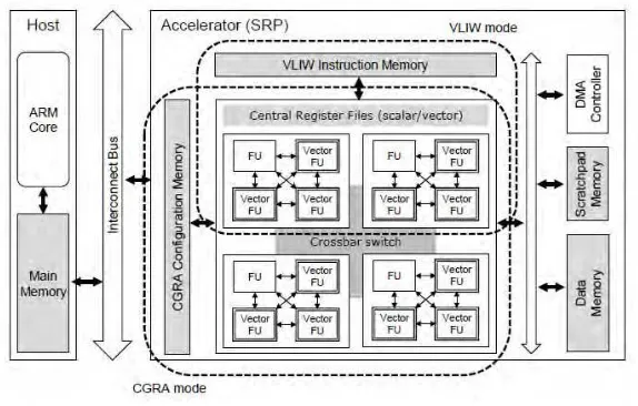
2.1.3 Methodology
The reconfigurable processor typically consists of multiple basic components, e.g., functional units (FUs) and register files (RFs). Those components comprise processing elements (PEs), which are connected by dedicated wires for fast communication. The PEs and overall topology can be configured flexibly during runtime. In such architectures, the major challenge is programming difficulty. Application programmers need to explicitly control the accelerator, manage communications between the host and the accelerator, and guarantee coherence and consistency between memory blocks. Figure 2.1 shows the target architecture for the project. Figure 2.2 shows the compilation process and Figure 2.3 shows the vectorization example.
6
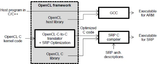
Figure 2.2: Compilation process
Figure 2.3: A vectorization example
2.1.4 Result
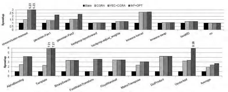
The baseline is C code obtained by base SnuCL translator, which is represented by the bar labelled Base. Most of the kernels are mapped to CGRA successfully and average speedup is 1.84. Six kernels of the benchmark applications are vectorised, average speedup of vectorization is 2.4 and the maximum speedup is 7.21. To increase efficiency of vectorization, the conditional statement optimization was applied, it is applied to Alpha Blending and it shows 4.21 speedup. The bar labelled WP+OPT shows the speedup over the baseline after applying work-item pruning and other optimizations. Average speedup of WP+OPT is 2.69 and the maximum speedup is 9.39. In case of Gaussian-Fan1 and Gaussian-Fan2, about half of the iteration range is pruned by work-item pruning. For VectorAdd, it can
[image:23.595.200.435.246.382.2]7
to 1% - 3% because they are not vectorized and pruned iteration ranges are small. Figure 2.4 shows the output result of OpenCL kernel speedup.
Figure 2.4: OpenCL kernel speedup
2.2 A Compiler Back-End for Reconfigurable, Mixed-ISA Processors with Clustered Register Files [2]
2.2.1 Introduction