Faculty of Electrical Engineering
GRID CONNECTED WITH MICRO SOLAR GENERATOR
Mohamad Findyrul bin Shariff
Master of Electrical Engineering (Industrial Power)
GRID CONNECTED WITH MICRO SOLAR GENERATOR
MOHAMAD FINDYRUL BIN SHARIFF
A dissertation submitted
in fulfillment of the requirements for the degree of Master of Electrical Engineering (Industrial Power)
Faculty of Electrical Engineering
UNIVERSITI TEKNIKAL MALAYSIA MELAKA
DECLARATION
I declare that this dissertation entitled “Grid Connected with Micro Solar Generator” is the result of my own research except as cited in the references. The thesis has not been accepted for any degree and is not concurrently submitted in candidature of any other degree.
Signature : ………..
Name : Mohamad Findyrul Bin Shariff
APPROVAL
I hereby declare that I have read this dissertation/report and in my opinion this dissertation/report is sufficient in terms of scope and quality as a partial fulfilment of Master of Electrical Engineering (Industrial Power).
Signature : ……….
Supervisor Name : ……….
DEDICATION
ABSTRACT
ABSTRAK
ACKNOWLEDGMENTS
Alhamdulillah and All praise to Allah S.W.T, the Almighty for HIS blessings and peace upon to our prophet, Prophet Muhammad S.A.W. It is my good challenge and experience to have a chance to complete this dissertation.
First of all, I would express my sincere gratitude and appreciation to my supervisors Engr. Professor Dr. Marizan bin Sulaiman and Associate Professor Dr Ismadi Bugis, for participating in giving constructive input, idea, advice and valuable guidance which mean to be invaluable to me in completion of this project in spite of his busy schedules. I thank to Universiti Teknikal Malaysia Melaka (UTeM) and Faculty of Electrical Engineering (FKE) for the financial support under PJP scheme.
I would like to express my appreciation and thankful to Dean, lectures, staff and technicians of FKE for their helps and supports during finishing my master degree. Also, thank to my postgraduate students colleagues for their helps in providing advices, support and collaboration until this dissertation completed.
Special dedication and acknowledgement to my beloved late father, Shariff bin Said and my mother, Hasnah binti Kamat as well as my family siblings in giving constant support, encouragement and their love.
TABLE OF CONTENTS
LIST OF APPENDICES xiii
LIST OF ABBREVIATIONS xiv
4.5 PV Connected to Three Phase Inverter 136 5. CONCLUSION AND RECOMMENDATION 144
5.1 Summary of Research 144
5.2 Achievement of Research Objectives 145
5.3 Significance of Research Output 146
5.4 Problem Faced During Research 146
5.5 Recommendations 147
REFERENCES 149
LIST OF TABLES
TABLE
3.1 3.2
3.3 3.4 4.1 4.2 4.3 4.4
TITLE
PV Module JHGF 12W/12V Parameters
Equivalent Switches Control and Output Voltages of Each Phase of Inverter
Switching Vectors, Phase Voltages and Line to Line Voltages Switching Time Calculation at Each Sector
PV Module Jiahei 12V Parameter Values at STC Characteristic of 7kW Photovoltaic Array
DC-DC Boost Parameters
Total Harmonic Distortion (THD) of System Performance Involved
PAGE
61 100
LIST OF FIGURES
Overview Flowchart of Research Methodology Topologies of PV Inverter Technologies
Configuration of Single Stage Photovoltaic System Configuration of PV String Inverter
Configuration of Multistring PV System Three Major Categories of PV Module
Equivalent Circuit of Single Diode Model (Villalva, Gazoli & Filho, 2009)
Equivalent Circuit Dual-Exponential Cell Model (Gow & Manning, 1999)
Proposed Schematic of Compensation Network Prototype (Femia, Petrone, Spagnuolo, et al., 2009)
Two Stages Grid Connected Photovoltaic System with DC-DC Converter (Liu, Kang, Zhang, et al., 2008)
PV Pumping System with DC-DC Converter (Elgendy, Zahawi & Atkinson, 2008)
Charging Battery System using Buck Converter (Koutroulis, Kalaitzakis & Voulgaris, 2001)
Schematic Circuit of Boost Converter for PV Application (Hasaneen & Elbaset Mohammed, 2008)
Switched Inductor Multilevel Boost Converter Schematic Diagram (Mousa, Orabi, Member, et al., 2011)
2.15
Cuk Converter Topology (Durán, Galán, Andújar, et al., 2007) 36 Schematic Diagram of SEPIC Converter (António, Vieira & Mota,
2008)
Typical Circuit Diagram of Three Phase VSI and CSI Inverters (Mechouma, Azoui & Chaabane, 2012)
Schematic Diagram of CSI for Proposed CSI (Ertasgin, Whaley, Ertugrul, et al., 2008)
Schematic Diagram of CSI with Series Capacitor (Photong, Klumpner & Wheeler, 2009)
Control Structure of Multilevel CSI Based PV System (Paramita Dash & Kazerani, 2011)
Proposed Hybrid Photovoltaic System Connected to Distribution Network (Tan, So, Member, et al., 2010)
Block Diagram of Proposed Solar Generating System (Adhikari, Singh, Vyas, et al., 2011)
The Configuration of 1kW Grid Connected PV System (Samerchur, Premrudeepreechacharn, Kumsuwun, et al., 2011)
Single Stage Structure of Photovoltaic System Dual Stage Structure of Photovoltaic System Irradiance Impact on the I-V Characteristics Curve Temperature Influences on the I-V Characteristic Curve Maximum Power Point of I-V Curve and P-V Curve Ideal Single Diode Model (ISDM)
Equivalent Model with Moderate Complexity Solar Cell Equivalent Circuit
Equivalent Circuit Model of Photovoltaic Module 63
PV Array Composed of Nser x Npar Modules PV Array Model Circuit of Nser x Npar Modules Simulink Block of PV Array
3.13
GUI Environment of PV Array
Circuit Diagram of Basic Boost Converter (Hart, 2010)
Basic Boost Converter when the Switch is Closed (Hart, 2010) Boost Converter Waveform during Switch Closed (Hart, 2010) Basic Boost Converter when the Switch is Open (Hart, 2010) Boost Converter Waveform during Switch Open (Hart, 2010) Continuous Conduction Mode
Discontinuous Conduction Mode Waveform Output of Boost Converter
Current-Voltage (I-V) Curve of PV Module (Faranda, Leva & Maugeri, 2008).
MPP of PV Module under Varying Insolation (Natsheh & Albarbar, 2011)
Plot of P-V Curve under Standard Operating Point Perturb and Observe MPPT Algorithm Flowchart Behaviour of Incremental Conductance Algorithm
Flowchart of IncCond Algorithm (Qin, Wang, Chen, et al., 2011) Simulink Block of Boost Converter
MPPT Controller in Simulink
Simulink Model of MPPT with Incremental Conductance and Integral Regulator
Single Phase Inverter Schematic Diagram (Hart, 2010) Single Phase Inverter Topology via Load or Grid Connected
3.35
Output Voltage of Single Phase Inverter (Salam, 2003)
Output Voltage and Current with Blanking Time (Abu-hamdeh, 2009)
Fundamental Component of Single Phase Inverter (Salam, 2003) Six Step Three Phase Inverter
Three Phase Inverter Switching Waveform (Hart, 2010) SPWM Control Signal Generator
Three Phase PWM Inverter (JUNG, 2005a)
Three Phase SPWM Waveforms Inverter (JUNG, 2005a) Simulink Model of SPWM Implementation
Three Phase Voltage Source PWM Inverter (JUNG, 2005b) Switching States of Three-Phase Inverter (JUNG, 2005b)
Relationship of abc Reference Frame and Stationary dq Reference Frame (JUNG, 2005b)
The Basic Switching Vectors and Sectors of SVPWM (JUNG, 2005b)
Space Vector Voltage and its d-q Component (JUNG, 2005b) Switching Pattern and Sector Duration of SVPWM
Simulink Model of SVPWM Implementation
Block Diagram of Suggested Control Strategy for Complete Grid Connected System
The Block Diagram of Grid Connected with Micro Solar Generator Block Diagram of Voltage Source Controller (VSC)
I-V Characteristic Curve of Jiahei 12V Module at STC P-V Characteristic Curve of Jiahei 12V Module at STC I-V Characteristic Curve of PV Array 7kW at STC P-V Characteristic Curve of PV Array 7kW at STC
4.5
I-V Characteristic Curve of Module at Various Irradiations P-V Characteristic Curve of Module at Various Irradiations I-V Characteristic Curve of PV Array at Various Irradiations P-V Characteristic Curve of PV Array at Various Irradiations Variation of Irradiation Generator
Ramp Change of Photovoltaic Voltage Output
Photovoltaic Output Current for Varied Irradiation at t=0s to 1.5s Duty Cycle of Boost Converter during Variation of Irradiation Photovoltaic Output Power for Varied Irradiation at t=0s to 1.5s Output Voltage of Boost Converter
THD for SPWM Modulation before Filtration THD for SPWM Modulation after Filtration THD for SVPWM Modulation before Filtration THD for SVPWM Modulation after Filtration Three Phase Inverter Output before Filtration
A Portion View of Three Phase Inverter Output before Filtration Total Harmonic Distortion of System before Filtration
Waveform for Modulation Index of Inverter Three Phase Inverter Output after Filtration
A Portion View of Three Phase Inverter Output after Filtration Total Harmonic Distortion of System after Filtration
Output Power after Synchronization with Grid Power
Zoom Out View of Output Power after Synchronization with Grid Power
Portion Waveform of Voltage and Current after Grid Synchronization
LIST OF APPENDICES
APPENDIX
A B C
TITLE
Matlab / Simulink Models
Simulation Model of Overall System DC-DC Boost Converter
PAGE
LIST OF ABBREVIATIONS Insulated Gate Bipolar Transistor Increment Conductance
Metal Oxide Semiconductor Field Effect Transistor Maximum Power Point Tracker
Proportional Integral Phase Lock Loop Photovoltaic Photovoltaic Array Perturb and Observe
Simplified Single Diode Model Sinusoidal Pulse Width Modulation Standard Temperature Conditions Space Vector Pulse Width Modulation Total Harmonic Distortion
LIST OF SYMBOLS
- Voltage at Maximum Power Point (V)
- Current at Maximum Power Point (A)
- Power at Maximum Power Point (W)
- Open Circuit Voltage (V)
- Short Circuit Current (A)
- Electron Charge - Boltzmann Constant - Sunlight Irradiation
- Coefficient of Current Temperature. - Variation of Temperature.
CHAPTER 1
INTRODUCTION
1.1 Background
1.2 Problem Statements
In the recent years, power demand is increasing regularly and it can be fulfilled by utilization of conventional or non-conventional energy source. As greenhouse effects and environmental issues are becoming a prime concern of all over the world, which led to escalate interest in renewable energy, which is one of options in reducing pollution. Furthermore, natural resources used in the production of power are dwindling and becoming more expensive when they are increasingly dried up in a very near future especially traditional fossil energy. There are few types of renewable energies; one of them is photovoltaic (PV) system or also known as solar energy system.
1.3 Objectives
Simulation framework of grid connected photovoltaic micro solar power station network systems which have following characteristics:
a) To develop a simulation model for an optimal grid connected with micro solar generator system.
b) To analyse an overall efficiency and utilization performance of system proposed.
1.4 Scope
1.5 Research Methodology Overview
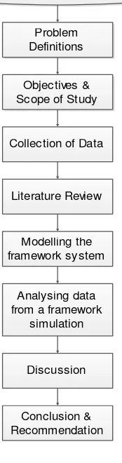
In this dissertation, mathematical model method is implemented throughout the modelling of overall framework of grid connected with micro solar generator. The research methodology flowchart overview of grid connected with micro solar generator is shown in Figure 1.1 .
Figure 1.1: Overview Flowchart of Research Methodology
The research methodology starts with problem definitions in order to know and focus an area of the study to be concentrated and come out with a few optional idea to solve the problem. Next, an objective and scope of study is clearly explained in section 1.3 and section 1.4.
Study on Grid Connected Micro Solar Generator
Objectives & Scope of Study
Collection of Data
Literature Review
Modelling the framework system
Analysing data from a framework
simulation
Discussion
Conclusion & Recommendation