ESTIMATION OF CONFIGURATION WORKSPACE FOR
A ROBOT-CONTROLLED VISION INSPECTION
SYSTEM
NUR SUFIAH AKMALA BINTI RAMDAN
B050910070
UNIVERSITI TEKNIKAL MALAYSIA MELAKA
ESTIMATION OF CONFIGURATION WORKSPACE FOR
A ROBOT-CONTROLLED VISION INSPECTION SYSTEM
This report submitted in accordance with requirement of the Universiti Teknikal Malaysia Melaka (UTeM) for the Bachelor Degree of Manufacturing Engineering
(Robotic and Automation) (Hons.)
by
NUR SUFIAH AKMALA BINTI RAMDAN
B050910070
900319-06-5126
UNIVERSITI TEKNIKAL MALAYSIA MELAKA
BORANG PENGESAHAN STATUS LAPORAN PROJEK SARJANA MUDA
TAJUK: NUR SUFIAH AKMALA BINTI RAMDAN
SESI PENGAJIAN: 2012/2013 Semester 2
Saya NUR SUFIAH AKMALA BINTI RAMDAN
mengaku membenarkan Laporan PSM ini disimpan di Perpustakaan Universiti Teknikal Malaysia Melaka (UTeM) dengan syarat-syarat kegunaan seperti berikut:
1. Laporan PSM adalah hak milik Universiti Teknikal Malaysia Melaka dan penulis. 2. Perpustakaan Universiti Teknikal Malaysia Melaka dibenarkan membuat salinan
untuk tujuan pengajian sahaja dengan izin penulis.
3. Perpustakaan dibenarkan membuat salinan laporan PSM ini sebagai bahan pertukaran antara institusi pengajian tinggi.
4. **Sila tandakan (√)
SULIT
TERHAD
TIDAK TERHAD
(Mengandungi maklumat yang berdarjah keselamatan atau kepentingan Malaysiasebagaimana yang termaktub dalam AKTA RAHSIA RASMI 1972)
(Mengandungi maklumat TERHAD yang telah ditentukan oleh organisasi/badan di mana penyelidikan dijalankan)
Alamat Tetap:
NO. 14, Jalan Kurnia 1, Taman Kurnia Jaya, 25150 Kuantan, Pahang
Tarikh: _________________________
Disahkan oleh:
Cop Rasmi:
Tarikh: _______________________
APPROVAL
This report is submitted to the Faculty of Manufacturing Engineering of UTeM as a partial fulfillment of the requirements for the degree of Bachelor of Manufacturing Engineering (Robotics and Automation) (Hons.). The member of the supervisory is as follow:
i
ABSTRAK
Konfigurasi ruang kerja adalah mengenai pergerakan robot. Ia adalah berkaitan dengan algoritma set pergerakan lengan robot. Algoritma harus direka untuk memenuhi keperluan untuk menggerakkan robot dengan gerakan yang diingini. Pergerakan lengan robot perlu direka bentuk untuk melakukan pemeriksaan berdasarkan pemprosesan imej digital oleh kamera. Projek ini akan disimulasi pada awalnya dengan menggunakan perisian Workspace, untuk memastikan bahawa ia mampu melakukan pergerakan yang diingini. Kemudian, hasilnya akan diterjemahkan ke dalam persekitaran sebenar dengan pengaturcaraan robot sebenar. Hasilnya ditunjukkan sebagai algoritma yang lengkap untuk menggerakkan robot dan bagaimana konfigurasi ruang kerja yang dilakukan untuk reka bentuk sistem ini. Keputusan telah diperolehi melalui pergerakan robot yang telah dibangunkan. Oleh itu anggaran yang terbaik daripada ruang kerja konfigurasi dapat diperolehi . Ini termasuk pergerakan, halaju dan pecutan sendi robot.
ii
ABSTRACT
Configuration workspace is related to the algorithm sets and movement of the robot. The algorithm must be designed to fulfill the requirement for moving the robot with the desired motion. For this robot-controlled vision inspection system, the movement of the robot arm must be design to do the inspection based on the image processing. The project will be first simulated using the Workspace software, to make sure that the robot can achieve the desired movement and angle. After that, the result will be translated into real environment, which is the programming of the real robot and the automatic inspection. The result is shown as a complete algorithm to move the robot
and how the workspace configuration is done to design this “Robotic Controlled
Vision Inspection System”. Therefore the best estimation of configuration workspace can be obtained from the results, including the position, velocity and acceleration of
the robot’s joints.
iii
DEDICATION
To my father Ramdan Razali , my mother Wan Maseri and all my siblings, I love you. Special to all Palestinian people, all Muslims and all good people in the world who are living in war, poverty and torture, I finished my Final Year Project is
iv
ACKNOWLEDGEMENT
v
TABLE OF CONTENT
Abstrak i
Abstract ii
Dedication iii
Acknowledgement iv
Table of content v
List of tables viii
List of figures x
List of abbreviation, symbols and nomenclature xvi
CHAPTER 1: INTRODUCTION 1
1.1 Background 1
1.1.1 The industrial vision inspection system evolution 2
1.2 Problem statement 4
1.3 Objective 4
1.4 Scopes 5
1.5 Expected outcome 5
1.6 Project planning 7
CHAPTER 2: LITERATURE REVIEW 8
2.1 Types of industrial robot 8
2.1.1 Robot manipulator 11
2.1.2 End effector 11
2.2 Serial robots in inspection process 12
2.3 Path and trajectory planning 13
2.3.1 The configuration workspace 13
2.3.2 Method of configuration space 14
vi
CHAPTER 3: METHODOLOGY 18
3.1 Identification of the method in path and trajectory planning 19
3.1.1 Experiment 1: Methods for path and trajectories planning 19
3.2 Design of the programming structure 23
3.2.1 Experiment 2: Robot programming 23
3.3 Development of the programs 26
3.3.1 Experiment 3: Program implementations 26 3.4 Assessment of the robot’s paths and trajectories 32 3.4.1 Experiment 4: Tests the robot in motion 32 CHAPTER 4: RESULT AND ANALYSIS 34 4.1 Identification of the method in path and trajectory planning 4.1.1 Experiment 1: Method for path and trajectory planning 34 4.1.1.1 Results 34 4.1.1.2 Discussions 34 4.2 Design of the programming structure 4.2.1 Experiment 2: Robot programming by Workspace 5 software 39 4.2.1.1 Results, analysis and discussions 39 4.2.1.1.1 Drawing of all parts by Workspace 5 39 4.2.1.1.2 The simulation set-up 54 4.2.1.1.3 The simulation movement 57 4.2.1.1.4 The simulation analysis 65 4.2.1.1.5 Discussions 103
4.3 Development of the program 104
4.3.1 Experiment 3: Program implementations 104
4.3.1.1 Results, analysis and discussions 104
4.3.1.1.1 The detail experimental set-up 104
4.3.1.1.2 The simulation movement 109
4.3.1.1.3 The simulation analysis 118
vii
4.4 Assessment of the robot’s paths and trajectories 157
4.4.1 Experiment 4: Test the robot in motion 157
4.4.1.1 Results 157
4.4.1.2 Discussions 158
CHAPTER 5: CONCLUSION AND FUTURE WORK 159
REFERENCES 160
APPENDICES 162
viii
LIST OF TABLES
3.1 3.2 3.3 3.4
The estimated trajectory
The results for planning the tool path The trajectories data
The table for data of robot movement
21
ix
x
LIST OF FIGURES
1.1 The machine vision inspection system evolution 2
1.2 1.3 1.4
A typical industrial vision sytem
A robot-controlled vision inspection sytem K-chart of the project
3 3 6
2.1 Comou 6-axis serial robot, model Smart5 NJ 9
2.2 ABB parallel robot, FlexPicker, model IRB 340 9
2.3 2.4 2.5
2.6
Mobile robot build by Neurotechnology Smart M1 Inline complete work envelope
The classification of inspection features and inspection elements
Example of workspace, configuration space and reference point
10 10 12 15
3.1 The flow of the project realization process 18
3.2 The car’s door that will be the object to be tested 20
3.3 Image of Workspace simulation taken from the Workspace software
The model of the robot The experimental set-up
The actual car’s door The car’s door sketching
The car’s door sketching with robot
The planned path for the inspection process Comau Smart M1 Inline
Comau Smart M1 Inline side view Comau Smart M1 Inline wireframe
Comau Smart M1 Inline top view with dimension
xi
Robot’s envelope for joint 1 and joint 2 Robot’s envelope for joint 3 and joint 4 Robot’s envelope for joint 5 and joint 6 Robot’s envelope for all joints
Gripper
Gripper top view with dimension Gripper wireframe view
Gripper with camera
Gripper with camera top view
Gripper with camera through wireframe view and dimension Car’s door
Car’s door with dimension Car’s door with wireframe view
The screws at the right side of the door The screws at the left side of the door The door holder
The door holder with dimension The door holder with wireframe view The door within inspection point
The simulation set-up for robot and car’s door
The simulation set-up for robot and car’s door (side view) The simulation set-up for robot and car’s door (top view) Robot’s envelope with the door
xii
Safety point 4 Safety point 5 Point 5 End point
Home position with complete path The Microsoft Excel file
Graph of joint value versus time for joint 1 with 20 % speed Graph of velocity versus time for joint 1 with 20 % speed Graph of acceleration versus time for joint 1 with 20 % speed Graph of joint value versus time for joint 2 with 20 % speed Graph of velocity versus time for joint 2 with 20 % speed Graph of acceleration versus time for joint 2 with 20 % speed Graph of joint value versus time for joint 3 with 20 % speed Graph of velocity versus time for joint 3 with 20 % speed Graph of acceleration versus time for joint 3 with 20 % speed Graph of joint value versus time for joint 4 with 20 % speed Graph of velocity versus time for joint 4 with 20 % speed Graph of acceleration versus time for joint 4 with 20 % speed Graph of joint value versus time for joint 5 with 20 % speed Graph of velocity versus time for joint 5 with 20 % speed Graph of acceleration versus time for joint 5 with 20 % speed Graph of joint value versus time for joint 6 with 20 % speed Graph of velocity versus time for joint 6 with 20 % speed Graph of acceleration versus time for joint 6 with 20 % speed Graph of all joint position in Workspace with 20 % speed Graph of joint value versus time for joint 1 with 30 % speed Graph of velocity versus time for joint 1 with 30 % speed Graph of acceleration versus time for joint 1 with 30 % speed Graph of joint value versus time for joint 2 with 30 % speed Graph of velocity versus time for joint 2 with 30 % speed Graph of acceleration versus time for joint 2 with 30 % speed Graph of joint value versus time for joint 3 with 30 % speed
xiii
Graph of velocity versus time for joint 3 with 30 % speed Graph of acceleration versus time for joint 3 with 30 % speed Graph of joint value versus time for joint 4 with 30 % speed Graph of velocity versus time for joint 4 with 30 % speed Graph of acceleration versus time for joint 4 with 30 % speed Graph of joint value versus time for joint 5 with 30 % speed Graph of velocity versus time for joint 5 with 30 % speed Graph of acceleration versus time for joint 5 with 30 % speed Graph of joint value versus time for joint 6 with 30 % speed Graph of velocity versus time for joint 6 with 30 % speed Graph of acceleration versus time for joint 6 with 30 % speed Graph of all joint position in Workspace with 30 % speed Experimental set-up
The door with 15cm marker The door with marker The camera
The camera front view Camera position
Student teaching the robot Home position
Initial position Safety Point 1 Safety Point 2 Point 1
Safety point 3 Safety point 4 Point 2 Safety point 5 Point 3 Safety point 6 Point 4 Safety point 7
xiv
Safety point 8 Point 5 End point Home position
Graph of joint value versus time for joint 1 with 20 % speed(r) Graph of velocity versus time for joint 1 with 20 % speed Graph of acceleration versus time for joint 1 with 20 % speed Graph of joint value versus time for joint 2 with 20 % speed Graph of velocity versus time for joint 2 with 20 % speed Graph of acceleration versus time for joint 2 with 20 % speed Graph of joint value versus time for joint 3 with 20 % speed Graph of velocity versus time for joint 3 with 20 % speed Graph of acceleration versus time for joint 3 with 20 % speed Graph of joint value versus time for joint 4 with 20 % speed Graph of velocity versus time for joint 4 with 20 % speed Graph of acceleration versus time for joint 4 with 20 % speed Graph of joint value versus time for joint 5 with 20 % speed Graph of velocity versus time for joint 5 with 20 % speed Graph of acceleration versus time for joint 5 with 20 % speed Graph of joint value versus time for joint 6 with 20 % speed Graph of velocity versus time for joint 6 with 20 % speed Graph of acceleration versus time for joint 6 with 20 % speed Graph of all joint position in real simulation with 20 % speed Graph of joint value versus time for joint 1 with 30 % speed Graph of velocity versus time for joint 1 with 30 % speed Graph of acceleration versus time for joint 1 with 30 % speed Graph of joint value versus time for joint 2 with 30 % speed Graph of velocity versus time for joint 2 with 30 % speed Graph of acceleration versus time for joint 2 with 30 % speed Graph of joint value versus time for joint 3 with 30 % speed Graph of velocity versus time for joint 3 with 30 % speed Graph of acceleration versus time for joint 3 with 30 % speed
xvi
LIST OF ABBREVIATIONS, SYMBOLS AND
NOMENCLATURE
° - Degree
CSO - Configuration space obstacle
Deg - Degree
DOF - Degree of freedom K-Chart - Khazani Chart
1
1.1 Background
Nowadays in many factories, human power is still being used to do the final inspection for the quality control. As human, they cannot avoid mistakes in their work. This is because human can get tired after sometime, cannot focus on the repeating work and the most important is, they cannot achieve the ability as the robot does, that is, they are slower than robot. Moreover, human expert are difficult to find or maintain in an industry, require training and their skills may take time to develop. There are also cases where inspection tends to be tedious or difficult, even for the best-trained expert (Malamas, 2005).
INTRODUCTION
2 1.1.1 The industrial vision inspection system evolution
Figure 1.1 shows how the evolution occur. Early before 1980’s, the industries throughout the world still using human power to do the inspection process in factories. Fabel (1997) wrote that, the evolution start in 1980’s ,after the machine vision was first marketed as a new, must-see technology for manufacturing
automation. Then when robot was introduced in 1960’s, the development of robot
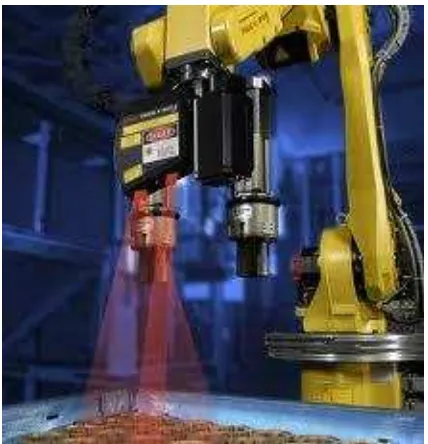
had also bring a development in machine vision system industry. Nowadays, people around the world had widely use the robot-controlled vision inspection system in their factory, to get more advantage. Figure 1.2 shows a typical industry vision system and Figure 1.3 shows a robot-controlled vision inspection system.
Figure 1.1: The machine vision inspection system evolution
HUMAN MACHINE
VISION
ROBOT-CONTROLLED
VISION INSPECTION
3 Figure 1.2: A typical industrial vision sytem. (Malamas, 2005).
4
1.2 Problem Statement
A typical industrial vision system is good, but the problem is some of the vision machine is not mobile and the capturing width is limited to certain angle. To overcome this problem, robot-controlled vision inspection system can be used. The idea is to attach the camera on the tip of the robot, so that the robot will move the camera and the camera will capture the image of the part. If any defect is detected from the image, image processing device will send signal to the output device so that the product will be categorized as “Not Good”. This research study is very important to make sure that the robot will do the best movement which consist of the consideration of its position, velocity and acceleration during the inspection process .
1.3 Objective