“I hereby declare that I have read this thesis and in my opinion this thesis is sufficient in terms of scope and quality for the award of degree of Bachelor
Mechanical Engineering (Structure & Material)”
Signature :………
Supervisor’s Name :………
THE FRACTURE MECHANIC ON THE SPOT WELDED JOINT
HAMZAH BIN SYAMSULRIZAL
Laporan ini dikemukakan sebagai memenuhi sebahagian daripada syarat penganugerahan Ijazah Sarjana Muda Kejuruteraan Mekanikal (Struktur &
Mekanikal)
Fakulti Kejuruteraan Mekanikal Universiti Teknikal Malaysia Melaka
ii
“I hereby declare that this project report entitled “the fracture mechanic on the spot welded joint” is written by me and it is my own effort except the ideas and summaries
which I have clarified their sources”.
Signature :………
Author :………
iii
To my beloved parents,
Syamsulrizal bin Mustafa.and Kamsiah bt. Zakaria Who inspired me with their love and kindness.
iv
ACKNOWLEDGEMENTS
I would like to generously thank the many people that assisted and supported my Projek Sarjana Muda (PSM). This PSM report is the product of hard work with several people. A special thanks to our beloved lecturer, Mr Ahmad Fuad Abd. Ghani, who was continually encouraging, insightful, and help me throughout this project. Without his guidance and useful advice, I don’t think my PSM report can be finished successfully and on time. I would like to thanks to my friends whom I had the pleasure to meet and work with in my project.
v
ABSTRACT
vi
ABSTRAK
vii
TABLE OF CONTENT
CHAPTER TOPIC PAGE
DECLARATION ii
DEDICATION iii
ACKNOWLEDGMENTS iv
ABSTRACT v
ABSTRAK vi
TABLE OF CONTENT vii
LIST OF TABLES x
LIST OF FIGURES xi
LIST OF APPENDICES xiii
CHAPTER 1 INTRODUCTION 1
1.1 Background 1
1.2 Objective 2
1.3 Scope 3
1.4 Problem Statement 3
CHAPTER 2 LITERATURE REVIEW 4
2.1 Introduction 4
2.2 Principle of Spot Welded 4
2.3 Structural Stress Parameter 6
2.4 Analyze Using Finite Element Method FEM 8
2.5 Material 13
2.6 Resistance Spot Welding 14
2.7 Weld Quality and Testing Method 18
viii
CHAPTER TOPIC PAGE
2.7.2 Other Tension Test 19
2.7.3 Hardness Test 21
2.7.4 Ductility Measurement 22
2.8 Tool Design and Heat Generation 22
CHAPTER 3 METHODOLOGY 24
3.1 Introduction 24
3.2 Flow Chart 25
3.3 Literature Review 26
3.4 Model Design Using Solidwork 26
3.5 Analyzing 27
3.5.1 Analysis Model in MSC Nastran Patran 28
3.5.2 Import the model 28
3.5.3 Creating Elements 29
3.5.4 Load and Boundary Conditions 30
3.5.5 Simulation 31
3.5.6 Result 31
3.6 Testing 32
3.6.1 Testing Specimen 33
3.6.2 Testing Procedure 34
3.6.3 Tensile Test Procedure 34
CHAPTER 4 RESULT AND DISCUSSION 36
4.1 Tensile Test Data Result 36
4.1.1 Data Result for Specimen 1 37
4.1.2 Data Result for Specimen 2 38
4.1.3 Data Result for Specimen 3 40
4.1.4 Data Result for Specimen 4 41
4.1.5 Data Result for Specimen 5 43
4.2 Comparison of Lap-Shear Data Result 44
ix
CHAPTER TOPIC PAGE
4.4 Comparison of Data Result and Analysis 50
CHAPTER 5 CONCLUSION 53
5.1 Overall Conclusion 53
5.2 Recommendation 54
REFERENCES 55
BIBLIOGRAPHY 58
x
LIST OF TABLE
NO TITLE PAGE
2.1 Ratio of Direct-Tension to Tension-Shear test specimen loads 22
3.1 Dimension of Specimen 27
xi
LIST OF FIGURES
NO TITLE PAGE
2.1 Local normal and shear stress in thickness direction at the edge
of a spot weld 7
2.2 Structural stress definition at the edge of spot weld nugget 7 2.3 Structural stress calculation procedure for fatigue crack in
thickness direction at the edge of the weld nugget 8
2.4 FEM around spot weld nugget 9
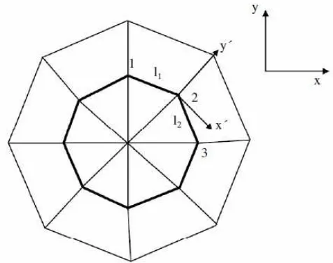
2.5 Local coordinate system at a grid point 10 2.6 Definition of the line forces at the nodal element 12
2.7 Front Door 13
2.8 Typical RSW Cycle. 15
2.9 Typical RSW setup 16
2.10 A tension-shear specimen 19
2.11 A cross tension specimen 20
2.12 A cross tension jig for thicknesses up to .19 in. (4.8 mm). 20
2.13 U-test specimen 21
2.14 Estimated instantaneous spot welding temperature in degrees
centigrade at the instant of completion of the weld 23
3.1 Flow Chart 25
3.2 Actual model of Specimen 26
3.3 Solidwork model of Specimen 27
3.4 import model to MSC Nastran Patran 28
3.5 Mesh on the solid model 29
3.6 The fix and load at then model 30
3.7 Result of the analysis model 32
xii 3.9 Spot Welding Specimens after cut from the front door 33
4.1 Graph of Load for specimen 1 37
4.2 Graph of Tensile Stress for specimen 1 37
4.3 Graph of Load for specimen 2 38
4.4 Graph of Tensile Stress for specimen 2 39
4.5 Graph of Load for specimen 3 40
4.6 Graph of Tensile Stress for specimen 3 40
4.7 Graph of Load for specimen 4 41
4.8 Graph of Tensile Stress for specimen 4 42
4.9 Graph of Load for specimen 5 43
4.10 Graph of Tensile Stress for specimen 5 43
4.11 Graph of Load for all specimen 44
4.12 Graph of Tensile Stress for all specimen 45
4.13 Necking on the specimen 3 46
4.14 A typical sheet fracture fatigue crack (left) and a photo of the
crack propagation along the surface of the base sheet material (right) 46 4.15 Spot weld specimen analysis – isometric view 48
4.16 Spot weld specimen analysis-side view 48
4.17 Spot weld specimen analysis – maximum 49
xiii
LIST OF APPENDICES
NO TITLE PAGE
A Standard Test Methods for Tension Testing of Metallic 59 Materials ASTM E8M-04
B List of Original Tensile Test Data Result 65
1
CHAPTER 1
INTRODUCTION
1.1BACKGROUND
Welding is a fabrication process that joins materials, usually metals or thermoplastics, by causing coalescence. This is often done by melting the work pieces and adding a filler material to form a pool of molten material (the weld puddle) that cools to become a strong joint, with pressure sometimes used in conjunction with heat, or by itself, to produce the weld.
There are many different energy sources can be used for welding, including a gas flame, an electric arc, a laser, an electron beam, friction, and ultrasound. While often an industrial process, welding can be done in many different environments, including open air, underwater and in outer space. Regardless of location, however, welding remains dangerous, and precautions must be taken to avoid burns, electric shock, eye damage, poisonous fumes, and overexposure to ultraviolet light.
2
Door of Proton car. The Finite Element Method (FEM) will carried out to analysis the structure and all stresses on the part of spot welded joint. The model will be designed according to the real dimension using the Solidwork. The complete model from solidwork will be exported to nastran patran software to analysis and calculate the stress on the spot welded.
1.2OBJECTIVE
This project carried out the study and analyze problem those related to the fracture mechanic on the spot welded joint. The other objectives that contain in this project are:
1. To understand the using of spot welded joint in Automotive. 2. To testing the spot weld using ASTM E8M-04 (Tensile Test) 3. To simulate the part using MSC Nasran/Patran software.
1.3SCOPE
The scopes of this study are:
1. To understand the spot welded characteristic and behavior. 2. Testing the spot weld using the ASTM E8M-04 (Tensile Test)
3
1.4PROBLEM STATEMENT
4
CHAPTER 2
LITERATURE REVIEW
2.1 INTRODUCTION
The literature review consists of various aspects regarding the effect of
geometrical variables the fracture analysis using the finite element method on the spot welded joint.
2.2 PRINCIPLE OF THE SPOT WELDED
Spot welding is a widely employed technique to join sheet metals for body and cap structure in the automotive industry. The strength of the spot welds in the unibody vehicle structure determines the integrity of the structural performance during the vehicle operations.
5
the spot welds lead to stress concentration that can result in fatigue crack initiation around the spot weld. The presence of fatigue cracks can degrade structural performance and increase noise and vibration of the vehicle structure. Therefore, understanding of the fatigue strength for the spot welds is very important in automotive component design.
The static strengths of spot welds have also been investigated. Ewing et al.[1] investigated the strength of spot welds in terms of the specimen geometry, welding parameter, welding schedule, base metal strength, testing speed and testing configuration. Zhang and Taylor [2] reported the thickness effect of spot welded structure on fatigue life. Pan and Sheppard [3] calculated stress intensity factors for crack propagation through the thickness of plate by numerically utilizing finite element analysis. Lee et al.[4]adopted a fracture mechanics approach using the stress intensity factor to model their experimental results on the strength of spot welds in U-tension specimens under combined tension and shear loading conditions. Wung[5] and Wung et al.[6] obtained and analyzed test results from lap-shear, inplane rotation, coach-peel, normal separation and inplane shear tests and proposed a failure criterion based on the experimental data of spot welds in various specimens.
Some researchers [7-9] have studied on the effects of base metal properties on the fatigue life of spot welds. They have also studied on the effects of loading conditions with different specimen types such as tensile shear, coach peel and cross tension specimens. These studied showed in general that fatigue life of spot welds depended on the loading conditions and base metal properties.
6
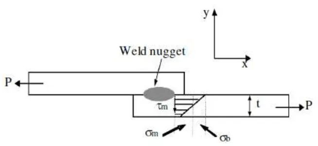
2.3 STRUCTURAL STRESS PARAMETER
Welded joints experience highly localized heating and cooling from welding processes. As a result, the material properties around the welding joints can be significant variations after welding. The local geometry of the welded joints may have variations due to the amount of heat inputs and welding skills. These variations present significant difficulties for reliable fatigue prediction of welded joints.
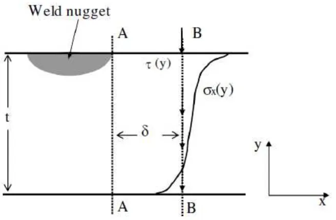
Dong[15-16] proposed a structural stress parameter for welded joins based on local stresses at weld toe. A typical through-thickness stress distribution at a fatigue critical location and the corresponding structural stress definition for through-thickness fatigue crack at the edge of a spot weld are shown in Fig. 2.1 and 2.2. Stress distribution at the edge of the spot weld nugget is assumed as shown in Fig. 2.1. In Fig. 2.2, t
represents the thickness of the sheet steel, σx and τ are the normal and transverse shear stress under axial force P respectively. The corresponding structural stress distribution is shown in Fig. 2.2. The structural stress (σ) is expressed in
Eq.2.1:
(2.1)
where, σm is the membrane stress component and σb is the bending stress component due to the axial force P in the x direction. The transverse shear stress can be calculated based on local structural shear stress distribution, however, the effect of transverse shear stress neglected since the spot weld does not experience significant transverse shear loads in general[15].
x-7
direction, evaluated along the plane B-B. On the other hand, Eq. 2.3 shows moment balances with respect to plane A-A at y = 0. When δ between planes A-A and B-B
[image:21.612.162.488.172.301.2]becomes smaller then transverse stress τ in Eq. 2.3 is negligible. Therefore, Eq. 2.2 and 2.3 can be evaluated at Plane A-A in Fig. 2.3
Figure. 2.1: Local normal and shear stress in thickness direction at the edge of a spot weld
(Source : Dong. P. (2001))
[image:21.612.163.490.436.587.2]8
Figure 2.3: Structural stress calculation procedure for fatigue crack in thickness direction at the edge of the weld nugget
(Source : Dong. P. (2001))
(2.2)
(2.3)
2.4 ANALYZE USING FINITE ELEMENT METHOD (FEM)
9
reasonable results but it requires a good amount of effort for modeling and computational time.
Therefore, the very detailed finite element modeling of spot welds is not feasible for 3000- 5000 spot welds in a typical automotive body structure[12]. Instead of the detailed modeling of the spot welds, a simple beam element represents a spot weld for fatigue calculation of the spot welds in a vehicle structure[12,14,20].
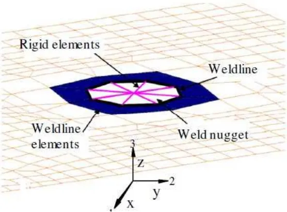
[image:23.612.187.483.373.592.2]For the mesh insensitive structural stress calculation, the specimen for a spot welded joint is modeled with shell/plate, beam and rigid elements. The circular weld mark in each plate is modeled by triangular shell elements and rigid beams forming a spoke pattern as shown in Fig. 2.4. The rigid beam elements are connected from the center node to the peripheral nodal points of the circular weld marks in the both plates. Then the center nodes of the circular weld marks in both plates are connected with a beam element.
Fig.2.4: FEM around spot weld nugget
10
Fig. 2.4 shows a finite element mesh around a circular weld mark. The geometry of the circular weld mark is required in the finite element model since the structural stress is calculated along the periphery of the weld. The normal direction of the shell elements (weldline elements) along the outside of the weldline is important for the calculation of the structural stress. Here, the weldline is defined as the periphery of the weld mark as shown in Fig. 2.4. A beam element represents the weld nugget to connect the top and bottom sheet steels. The length of the beam element is determined to be equal to one half of the total thickness for two sheets.
[image:24.612.217.455.338.526.2]The nodal forces and moments in a global coordinate system at each mesh corner along the weld line (nugget periphery) with respect to the shaded elements in Fig. 2.4 are directly obtained from a linear elastic finite element analysis.