UNIVERSITY TEKNIKAL MALAYSIA MELAKA
OPTIMIZATION OF MACHINING PARAMETERS IN HIGH
SPEED MILLING OF ALUMINUM 6061
This report submitted in accordance with requirement of the Universiti Teknikal Malaysia Melaka (UTeM) for the Bachelor Degree of Manufacturing Engineering
(Manufacturing Process) with Honours
By
LIM CHONG WEI
UTeM Library (Pind.1/2007)
UNIVERSITI TEKNIKAL MALAYSIA MELAKA
BORANG PENGESAHAN STATUS TESIS*
JUDUL: Optimization of machining parameters in high speed milling of Aluminum 6061._______________________
SESI PENGAJIAN: 2008/09___________________________________________________
SayaLIM CHONG WEI (B050510063)_________________________________________
mengaku membenarkan tesis (PSM/Sarjana/Doktor Falsafah) ini disimpan di Perpustakaan Universiti Teknikal Malaysia Melaka (UTeM) dengan syarat-syarat kegunaan seperti berikut:
1. Tesis adalah hak milik Universiti Teknikal Malaysia Melaka .
2. Perpustakaan Universiti Teknikal Malaysia Melaka dibenarkan membuat salinan untuk tujuan pengajian sahaja.
3. Perpustakaan dibenarkan membuat salinan tesis ini sebagai bahan pertukaran antara institusi pengajian tinggi. atau kepentingan Malaysia yang termaktub di dalam AKTA RAHSIA RASMI 1972)
APPROVAL
This PSM submitted to the senate of UTeM and has been as partial fulfillment of the requirements for the degree of Bachelor of
Manufacturing Engineering (Manufacturing Process)
The members of the supervisory committee are as follow:
………
DECLARATION
I hereby, declared this thesis entitled “Optimization of machining parameters in high
speed milling of aluminum 6061” is the results of my own research except as cited in references.
Signature : ……….
Author‟s Name : LIM CHONG WEI
ABSTRACT
ABSTRAK
Laporan ini menerangkan pengoptimuman parameter dalam „milling‟mesin untuk aluminum 6061. Aluminum digunakan dengan meluas dalam industri seperti automasi, aeroangkasa dan lain-lain industri. „High speed milling‟ dipilih kerana ia boleh menghasilkan produk secara besar-besaran dengan presis jika dibandingkan dengan mesin „milling‟ yang biasa. Objektif eksperimen ini adalah untuk menganalisis permukaan Aluminium dengan menggunakan „surface roughness
tester‟ untuk parameter setting yang berlainan seperti kelajuan spindle, kedalaman pemotogan dan kecepatan material dibuang. Dengan ini,optimum parameters boleh didapatkan. Dalam kerja kursus ini, cara untuk mengalisis adalah menggunakan RSM. Terdapat 20 percubaan akan dibuat dengan menggunakan tiga-axis mesin
„milling‟. Kekasaran permukaan yang dihasilkan akan diuji dengan menggunakan
DEDICATION
ACKNOWLEDGEMENT
Without involvement of many people, this project would not have been possible to complete. I would like to thank all of you especially to my supervisor, Ms Liew Pay Jun. Thanks for her guidance, advice, trust, sincere helping and excellent supervision in accomplishing this study. She is always willing to help me whenever I approach her.
Besides that, I would like to thank all my lecturers of Manufacturing Engineering Faculty and others that provided me with useful information and experience especially in contributing and sharing ideas toward this project.
Furthermore, I would like to extend my thankful to Manufacturing Engineering Laboratory of Universiti Teknikal Malaysia Melaka (UTeM) for providing me the equipments, time and always show their sincere kindness. Then, I also would like to thank my friend for sharing their time, ideas and comments to help me complete the experiment of this project.
2.4 Survey of appropriate cutting tool 16
3.2.1 Define the objective of the experiments 32
3.2.2 Determine the parameters speed at low level and high level 32
3.2.3 Identify the respond variable 32
3.2.4 Preparation of the experiments 32
3.2.4.1Workpiece preparation 33
3.2.4.2Cutting tool preparation 34
3.2.4.3Equipments and procedures 34
3.2.5 Running the experiments 35
3.2.5.1Testing 35
3.2.6 Define and analysis the results 36
3.2.7 Develop mathematical model of response surface with best fittings 36 3.2.8 Finding the optimal set of experimental parameters 36
4.4.1 Average Deviation Percentage Value 60
5.0 RECOMMANDATION AND CONCLUSION 61
5.1 Conclusion 61
5.2 Recommendation of Method Used 62
5.3 Recommendation of Safety 63
References 64
Appendix 68
LIST OF TABLES
2.1 Al 6061 chemical composition (%) 14
2.2 Mechanical properties at room temperature 15
2.3 Standard tempers and its definitions 15
2.4 Chemical properties of High Speed Steel (HSS) 17
3.1 Factors and their entire unit and speed 32
3.2 Data guide to run the experiments 35
4.1 Surface Roughness Value Of Different Setting 38
4.2 Sequential Model Sum of Square [Type 1] 41
4.3 Lack of fit test 41
4.4 Model Summary Statistic 42
4.5 Analysis of variance table [Partial sum of squares - Type III] 44
4.6 Summarize value of Analysis of variance table 45
4.7 Solution Value Suggested By Design Expert Software 56
4.8 Surface Roughness Value for Random Trail 59
LIST OF FIGURES
2.1 VCM with parts name 7
2.2 Movement of the VCM machine 7
2.3 Conventional milling 8
2.4 Climb milling 9
2.5 Face mill with indexable inserts 9
2.6 End Milling 10
2.7 Range of cutting speed for difference materials 13 2.8 Different Cutting Tool with Different Hardness and Fracture Strength 16 2.9 Definition of the arithmetic average height (Ra) 19 2.10 Three spots for taking surface roughness measurements 19 2.11 Principle of a stylus instrument profilometer 20 2.12 Relationship between a response variable and the two independent 22 variables x1 and x2.
3.1 Phase of experiments 30
3.2 Flow Chart of conducting experiments 31
3.3 Flow chart of workpiece preparation 33
3.4 HSS end mill diameter 6mm 34
3.5 HAAS VF Series Vertical Machining Center 34
4.1 Graph Box-Cox Plot for Power Transform 40 4.2 Predicted Versus Actual Graph For Quadratic Model 42 4.3 Predicted Versus Actual Graph For Linear Model 42
4.4 Normal Plot of Residuals For Quadratic Graph 43
4.5 Normal Plot of Residuals For Linear Graph 43
4.6 One Factor graph of cutting speed (A) versus surface roughness 46 4.7 One Factor graph of feed rate (B) versus surface roughness 48 4.8 One Factor graph of depth of cut (C) versus surface roughness 50
4.9 Perturbation graphs of Factor A, B and C 52
4.10 3D modeling and Contour graph of cutting speed (A) and depth of cut (C) 53 to respond of surface roughness
4.11 3D modeling and Contour graph of cutting speed (A) and feed rate (B) 54 to respond of surface roughness
4.12 A Cube Box Show The Interaction Between Cutting Speed (A),Feed Rate 55 (B) And Depth of Cut
4.13 Ramp Function Graph 57
4.14 3D modeling and Contour graph of cutting speed (A) and feed rate (B) 57 to the desirability.
LIST OF ABBREVIATIONS
CHAPTER 1
INTRODUCTION
This chapter describes the introduction to the title of the project and briefly explains on the problem faced on the industry and also the planning of completing PSM 1 .This chapter also includes the scope and important of carried this project.
1.1 Introduction
High speed machining was first develop by German inventor during year 1920 and now widely spread in variety of manufacturing industry included aerospace and automotive sectors where to produce high precession and accuracy parts. Major advantages of high speed machining are high material removing rate, reduction of lead time and the most important is increase parts precision and surface finish. Many industry nowdays facing challenge to improve the quality of products and processes with minimum cost and time constraints.
solve the problem of surface roughness. It is advance to select the parameters of cutting speed; spindle speed and depth of cut because these are the main factors that affect the surface roughness and also can be controllable.
The goal of the research is to determine the possible effect of high speed milling on the aluminum surface by conducting the surface roughness test of the workpieces that produce. This included using the surface roughness tester to check for the surface roughness produce by different speed of cutting and the defects on the surface may lead to major changes in the mechanical properties of the material such as reduction in fatigue life. The results from this research will assist to replace the traditional ―trial and
error‖ method by DOE method which may lead to the improvements in manufacturing
of aircraft and manufacturing industry. Aluminum 6061 is chosen as the material to test because it is widely used for construction of aircraft structures, such as wings and fuselages, more commonly in automation precision parts.
1.2 Background of Problem
spindle speed and depth of cut to the surface roughness by using RSM method in order to get the best optimum parameter setting for surface roughness.
1.3 Statement of Problem
What is the effect of different parameters setting such as depth of cut, spindle speed and feed rate to the surface roughness?
What is the best setting of parameters to get the perfect surface roughness?
1.4 Objective
To analyze the effect of feed rate, depth of cut and spindle speed to the surface roughness of Aluminum.
To determine the optimum parameters of surface roughness.
1.5 Scopes
For this experiment, the factors that involved are spindle speed, depth of cut and also feed rate. Material that will be used is Aluminum 6061.RSM method will apply to get the optimum speed of parameters. Cutting tool involved is high speed steel with diameter 6mm. The factors that would not cover are material used, tool geometry, cutting tool diameter, voltage of high speed machining tool design and others.
1.6 Importance of Study
help the industry to save time and cost compare to the previous ―trial and error‖ method which need experience machinist to test the surface finish using different of parameters speed.
1.7 Expected Result
CHAPTER 2
LITERATURE REVIEW
This chapter describes the theory of milling machine and how the parameters are selected by referring to the journal .Besides that, the machining, tool, workpiece properties and summary of journal are also explained and show in this chapter.
2.1 Milling Machine
Milling machine is capable of performing a variety of cutting operations and is among the most versatile and useful machine tools. The first milling machine was built in 1820 by Eli Whitney (1765-1825). Its basic form is that of a rotating cutter which rotates about the spindle axis (similar to a drill), and a table to which the workpiece is affixed. The workpiece is held securely on the work table of the machine or in a holding device clamped to the table. It is then brought into contact with a revolving cutter. [1]
2.1.1 Machining Center
A machining centers is an advanced, computer controlled machine tools that is capable of performing a variety of machining operations on different surfaces and different orientations of a workpiece without having to remove it from its workholding device or fixture. The workpiece is generally stationary, and the cutting tools rotate as they do in milling, drilling, honing, tapping, and similar operations. Whereas in transfer lines or in typical shops and factories the workpiece is brought to the machine, note that in machining centers, it is the machining operation that is brought to the workpiece. CNC machine allow more operation to be done on a part in one setup instead of moving from machine to machine for various operations. These machines greatly increase productivity because the time formerly used to move a part from machine to machine is eliminated. [1]
There are three main types of machining centers which is horizontal, the vertical spindle and universal machines. They are available in many types and sizes which may determine by following factors:
The size and weight of the largest piece that can be machined.
The maximum travel of the three primary axes (X, Y, Z).
The maximum speed and feeds available.
The horsepower of the spindle.
The number of tools that the automatic tool changer (ATC) can hold.
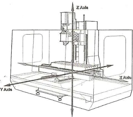
Figure 2.1: VCM with parts name
The vertical machining center operates on three axes which show in Figure2.2:
The X axis controls the table movement left or right.
The Y axis controls the table movement toward or away from the column.
The Z axis controls the vertical movement (up or down) of the spindle or knee.
2.1.2 Milling machining operation
There are three basic types of milling operations, which is a) Peripheral milling
b) Face milling c) End milling
2.1.2.1Peripheral milling
Peripheral milling also called plain milling which the axis of cutter rotation is parallel to the workpiece surface as show in figure. The cutter body which generally is made of high speed steel has a number of teeth along its circumference; each tooth acts like a single-point cutting tool. Cutter of peripheral milling may have straight or helical teeth, resulting in orthogonal or oblique cutting action.
There are two type of peripheral milling:
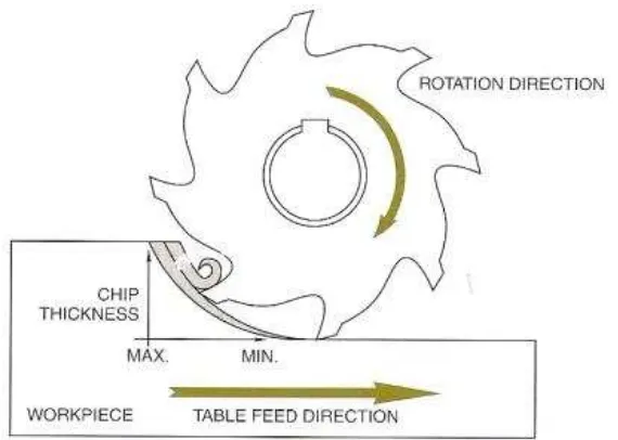
Conventional milling
Climb Milling
Figure 2.4: Climb milling
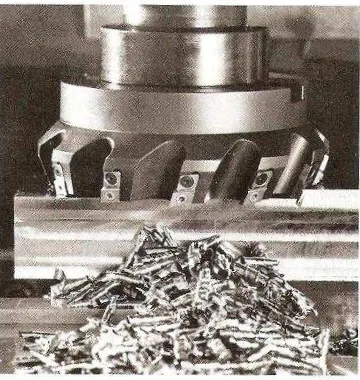
2.1.2.2Face milling
The cutter is mounted on the spindle having an axis of rotation perpendicular to the workpiece surface and removes material as in figure 2.5. Because of the relative motion between the cutter teeth and workpiece, face milling leaves feed marks on the machined surface. The surface roughness of the workpiece depends on the corner geometry of the inserts and feed per tooth. In typical face-milling operation, the ratio of the cutter diameter, D to the width of cut, w should be not less than 3:2. [1]