i
SMART CONTROL VENTILATION FOR ROOM
IZAL FIRDAUS BIN HAJI ISHAK
This report is submitted in partial fulfillment of the requirements for award of Bachelor of Electronic Engineering (Electronic Industry) with honour.
Faculty Of Electronic and Computer Engineering
University Teknikal Malaysia Melaka
ii
UNIVERSTI TEKNIKAL MALAYSIA MELAKA
FAKULTI KEJURUTERAAN ELEKTRONIK DAN KEJURUTERAAN KOMPUTER
BORANG PENGESAHAN STATUS LAPORAN
PROJEK SARJANA MUDA II
Tajuk Projek : SMART CONTROL VENTILATION FOR ROOM
Sesi Pengajian : 2008/2011
Saya ………IZAL FIRDAUS BIN HAJI ISHAK…………...
mengaku membenarkan Laporan Projek Sarjana Muda ini disimpan di Perpustakaan dengan syarat-syarat kegunaan seperti berikut:
1. Laporan adalah hakmilik Universiti Teknikal Malaysia Melaka.
2. Perpustakaan dibenarkan membuat salinan untuk tujuan pengajian sahaja.
3. Perpustakaan dibenarkan membuat salinan laporan ini sebagai bahan pertukaran antara institusi pengajian tinggi.
4. Sila tandakan ( √ ) :
SULIT*
(Mengandungi maklumat yang berdarjah keselamatan atau kepentingan Malaysia seperti yang termaktub di dalam AKTA RAHSIA RASMI 1972)
TERHAD* (Mengandungi maklumat terhad yang telah ditentukan oleh
organisasi/badan di mana penyelidikan dijalankan)
TIDAK TERHAD
Disahkan oleh:
__________________________ ___________________________________
(TANDATANGAN PENULIS) (COP DAN TANDATANGAN PENYELIA)
iii
“I hereby declare that this report is the result of my own work except for quotes as
cited in the reference”
Signature : ………..
Author : IZAL FIRDAUS BIN HAJI ISHAK
iv
“I hereby declare that I have read this report and in my opinion this report is
sufficient in terms scope and quality for the award of Bachelor of Electronic
Engineering (Electronics Industry) With Honours”
Signature : ………
Name : CIK MUZALIFAH BINTI MOHD SAID
v
ACKNOWLEDGEMENT
Alhamdulillah. Thanks to Allah SWT, with his willing that giving me the
oppurtunity to complete the Final Year Project which is title Smart Control
Ventilation System for Room. This report were prepared for Faculty of Electronic
and Computer engineering, University Teknikal Malaysia Melaka (UTeM), for
student in final year to complete the degree of bachelor of Engineering in electronic
Industry.
I would like to express my deepest thanks to, Miss Muzaliffah binti Mohd
Said as my supervisor who had guided me in this project during the two semester
2010/2011. At the same time, I would never forget all the guidance and support that
have be given in all the time. Moreover, she had given me a strong motivation to
complete the project.
Deepest thanks and appreciation to my beloved father and mother, family
members, friends and others for their cooperation, encouragement, constructive
vi
ABSTRACT
Ventilation is an air circulation from outdoors into the building. Inside the
building, the ventilation system was created to control the movement of air to clean
air and unpolluted, and the system is added either by using cold air. On this day, the
ventilation system can only be controlled in the operating room immediately. This
means that the temperature control system can only be controlled in the operating
room and cannot be controlled in the room itself. For example, in a room in the
building, there is a student with a fever. He had to sit in a cold room because for
controlling the temperature can only be done in the operating room immediately.
This problem can be solved with this project. Project is to improve the ventilation
system so that it can be controlled from the room by using a combination of infra-red
remote controller, microcontroller PIC16F877A and the DC motor. This system can
control the entry of cold air into the room only by adjust the adjustable. This project
is hoped to improve and to facilitate the public who cannot tolerate cold
vii
ABSTRAK
Ventilasi ialah pergerakan udara dari luar bangunan ke dalam bangunan. Di
dalam bangunan, ventilasi sistem telah di wujudkan untuk mengawal pergerakan
udara supaya udara sentiasa bersih dan tidak tercemar serta sistem ini di tambah baik
dengan menggunakan udara sejuk. Pada hari ini, ventilasi sistem hanya boleh di
kawal di dalam bilik operasi sahaja. Ini bermakna, sistem pengawalan suhu hanya
boleh di kawal di dalam bilik operasi dan tidak boleh di kawal di dalam bilik sendiri.
Sebagai contoh, di dalam sebuah bilik di dalam bangunan, ada seorang murid yang
demam. Dia terpaksa duduk di dalam bilik yang sejuk kerana pengawalan suhu
hanya boleh di lakukan di dalam bilik operasi sahaja. Dengan menggunakan projek
yang telah saya lakukan, masalah ini boleh di atasi. Objektif utama projek ini ialah
untuk memperbaiki sistem ventilasi supaya ia dapat di kawal dari dalam bilik
dengan menggunakan kombinasi alat pengawal jauh infra red, mikrokawalan
PIC16F877A dan menggunakan DC motor. Sistem ini boleh mengawal kadar
kemasukan udara sejuk yang masuk ke dalam bilik dengan melaraskan gril yang
telah di reka. Projek ini di harap dapat menambahbaikan dan dapat memudahkan
viii
TABLE OF CONTENT
CHAPTER PAGE
Project Title i
Borang Pengesahan Status Laporan ii
Declaration iii
Acknowledgement v
Abstract vi
Abstrak vii
List of Content viii
List of Figure xii
List of Appendix xiv
1. INTRODUCTION
1.1 Background Project 1
1.2 Problem Statement 2
1.3 Objective 2
1.4 Scope 3
1.5 Project Methodology 5
ix
2.3.2 Infrared Circuit 2 15
2.3.3 Temperature Circuit 1 16
2.4.2 Introduction to PIC Micrcontroller 23
x
2.5 Temperature Sensor: DS 1820 28
2.5.1 DS 1820 Features 28
2.5.2 DS 1820 Description 29
2.6 Proteus 6 Professional 29
2.7 Liquid Crystal Display (LCD) 30
2.8 Printed Circuit Board (PCB) 31
3. METHODOLOGY
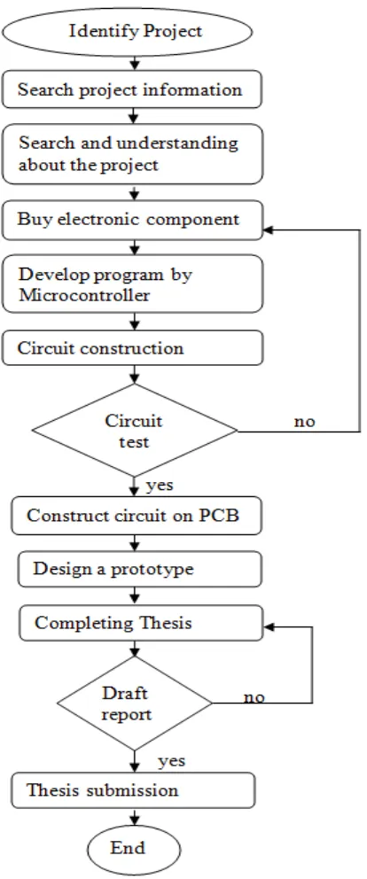
3.1 Flow Chart Methodology 32
3.2 Identify the Title 35
3.3 Searches for Information 35
3.4 Understanding Basic Matter of Project 35
3.5 Identify the Circuit and Buy Electronic
Component 36
3.6 General Process in Fabrication the Process 37
xi
4.2.2 Simulation on Temperature Circuit 44
4.3 Result on Hardware 45
5. DISCUSSION AND CONCLUSION
5.1 Discussion 50
5.2 Conclusion 51
xii
LIST OF FIGURE
NO.OF FIGURE TITLE PAGE
1.1 Flow Chart for Project Methodology 5
2.1 Infrared Light 9
2.2 Modulation signal 9
2.3 Transmit infrared signal 11
2.4 Transmitter with emitter follower 12
2.5 Block diagram of IR receiver 12
2.6 IR Transmitter 13
2.7 Remote control decoder for up to 20
subaddresses with 6 + 1-bit parallel
outputs (RECS80 code). 14
2.8 Receiver Circuit 15
2.9 Digital Room Thermometer Circuit 16
2.10 Temperature Circuit 17
2.11 Motor Circuit 19
2.12 PIC burner 24
2.13 PIC16F877A 25
xiii
2.15 DS 1820 Pin Assignment 28
2.16 Liquid Crystal Display (LCD) 30
3.1 Flowchart of project methodology 33
3.2 Continue from flowchart of project methodology 34
3.3 Several components that related to circuit project 36
3.4 Ultra Violet ray exposure 37
3.5 Developer 38
3.6 Etching Equipment 39
3.7 Cutting PCB board 40
3.8 Drilling the PCB board 40
4.1 Motor Circuit 43
4.2 Temperature Circuit 44
4.3 Top view of Temperature Circuit 45
4.4 Bottom view of Temperature Circuit 45
4.5 Top view Motor Circuit 46
4.6 Top view of Transmitter Circuit 47
4.7 Bottom view of Transmitter Circuit 47
4.8 Top view of Receiver Circuit 48
xiv
7. LIST OF APPENDIX
APPENDIX A: DIFFERENCES OF TEMPERATURE SENSOR 53
APPENDIX B: GANTT CHART FOR FINAL YEAR PROJECT 54
APPENDIX C: TEMPERATURE CIRCUIT SOURCE CODE 55
APPENDIX D: MOTOR CIRCUIT SOURCE CODE 62
APPENDIX E: PIC 16F877A 64
APPENDIX F: DIFFERENCES BETWEEN PIC16F877 AND PIC16F877A 75
1
CHAPTER I
INTRODUCTION
1.1 Background Project
Ventilation systems are an integral part in the building. Ventilation is the
process to refresh the environment in a room by reducing the temperature to improve
the quality of air in the room. This system is designed to control the temperature in
the room automatically.
The system will be placed in the AC vents at the system output. There are
devices installed on the line output hole ventilation system. To control the flow of
cold air and the temperature in the room, this device has a grill adapted to close or
open the hole. This will allow cold air into the room can be brought under control
2
1.2 Problem Statement
Ventilation systems in buildings controlled by centralized control systems.
Therefore, the ventilation system cannot control the temperature in each room. Then
the room temperature is always changing and sometimes drastic changes (eg days of
rain or night). Thus, the environment is not comfortable as the temperature is very
cold will take place on human life. Second, the controls are used at present by the
people there are some unexpected things happen. For example, when a rainy day, the
ventilation system will lower the temperatures by using the manual method and vice
versa. For this reason, an automatic control system is needed.
1.3 Project objective:
Due to the problem statement stated above, it’s cleared that the objectives of
the project is:
To develop and implement an automatic control ventilation system.
To design a smart and intelligent system of automatic control room
temperature.
To build an accurate and sensitive circuit to control the room’s temperature
according to any changes of temperature that user want.
To write a program in C programming language for the peripheral interface
microcontroller(PIC) to detect the changes on temperature and to run the motor
3
1.4 Scope of work
There are several process was involved to complete this Smart Control
Ventilation for Room. This system was consisting of several devices such as PIC,
LCD display, Infrared connection and DC geared Motor.
Beside the hardware, there are two programs that used in the project. The
software is Proteus Professional 6 and PIC C Compiler. Proteus Professional 6 is
used to simulation of work and to design the circuit on PCB board. While PIC C
Compiler is used to compile the C language code to HEX code so that it can be
compatible with the PIC program.
The following shows all the circuit that applied in this project:
a. Transmitter and Receiver Circuit
This circuit was used to transmit the signal from user to the system.
The Transmitter and Receiver Circuit was used infrared medium and the
signal that has transmitted will receive and send to the PIC.
b. Temperature Circuit
It is to detect the changes of temperature. After detect the temperature,
it will send the data to PIC microcontroller to compare with data from
4
c. Motor Circuit
Motor Circuit will run when it received signal from PIC
Microcontroller. Motor will run backward or forward according the data that
were received.
d. Power Supply Circuit
The power supply circuit is used to supply the voltage to all of the
5
1.5 Project Methodology
6
1.6 Project Outline
As provided in the format of the thesis, there are five chapters as whole. In
the first chapter, it focuses on a brief introduction about the project being carried.
Important things in this chapter is the problem statement, purpose and scope of the
project objectives are emphasized in this section.
Chapter II is usually focused on the literature review, including relevant
theory and previous work on the project described in this chapter. It discusses the
theory of infrared remote control, IR range of reference, the reference temperature
range and the microcontroller is used.
Chapter III consists of the project methodology. It also includes information
on research and experiments conducted during the project development. This would
explain the theory of concepts and principles used in order to complete the project. In
this chapter, the function of each part used has been explained clearly.
Chapter IV consists of the results and analysis. It describes and details the
components of focus for the project.
Chapter V consists of discussions and conclusions for this project. This will
explain to this chapter includes discussions, conclusions, witnesses and further
7
CHAPTER II
LITERATURE REVIEW
2.1 Introduction
Literature Review is important in each project as a base for gathering information
necessary to complete the project. All information is gathered from various sources
such as:-
1. Journal
2. Books
3. Conference Transcript
4. Thesis
5. Patent
8
After searching through all this various material, all information will be
filtered to be related to Smart Control Ventilation System for Building. The
information that will be focused on this chapter is about some reference circuit of
automatic controlled room temperature and its main components that to be used.
2.2 IR Remote control theory
The cheapest way to remotely control a device within a visible range is via
Infra-Red light. Almost all audio, video and temperature equipment can be controlled
this way nowadays. Due to this wide spread use the required components are quite
cheap, thus making it ideal for own projects. This part of knowledge base will
explain the theory of operation of IR remote control, and some of the protocols that
are in used in consumer electronics.
2.2.1 Infrared light
Infra-Red actually is normal light with a particular colour. Human cannot see
this colour because the wave length of 950nm and it below the visible spectrum. That
is one of the reasons why I choose the Infrared connection because human want to
use it but they are not interested in seeing it. Another reason is because IR LEDs are
quite easy to find, and it is was be very cheap.
A video camera or digital photo camera can "see" the Infra-Red light as see in
the below picture. Unfortunately, there are many more sources of Infra-Red light.
The sun is the brightest source of all, but there are many others, like light bulbs,
candles and central heating system. In fact, everything that radiates heat, also radiates
2.2.2 Modulation
on is the best answer to make the signal stand out
ignal, the IR light source blink in a particular
uned to that frequency. This blinking as attrac
Figure 2.2: Modulation signal
e 2.2, the modulated signal was sending the sig
the left side. The signal was detected signal of
ommunication, it were usually speak of 'marks
ult signal, which is the off state in the transmitte
'space' state. During the 'mark' state of the sig
t a particular frequency. Frequencies between 30kH
10
are commonly used in electronics. At the receiver side a 'space' is represented by a
high level of the receiver's output. A 'mark' is then automatically represented by a
low level.
The real relationship between the 'marks' and 'spaces' and the 1-s and 0-s
depends on the protocol that is being used.
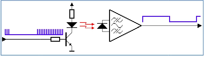
2.2.3 Transmitter
The transmitter usually is a battery powered handset. It was consume as little
power, and the IR signal should also be as strong as possible to achieve an acceptable
control distance.
Many circuit are designed to be used as IR transmitters. Nowadays, very low
power microcontrollers are used in IR transmitters and the reason that, they are more
flexible in their use. When no button is pressed, the circuit are in a very low power
sleep mode, in which hardly any current is consumed. The processor wakes up to
transmit the appropriate IR command only when a key is pressed.
Quartz crystals are seldom used in such handsets. They are very fragile and
tend to break easily when the handset is dropped. Ceramic resonators are much more
suitable, because they can withstand larger physical shocks.
The current through the LED can vary from 100mA to well over 1A. In order
to get an acceptable control distance the LED currents have to be as high as possible.
A trade-off should be made between LED parameters, battery lifetime and maximum
control distance. LED currents can be that high because the pulses driving the LEDs
are very short. Average power dissipation of the LED should not exceed the
maximum value though. Note that the maximum peek current for the LED is not