1107 1
! " # $% µµµµ
&' (
) $* µµµµ+
, " $%%
-. #
I. INTRODUCTION
PIEZOELECTRICS [1] are attractive materials for fabricating vibration energy harvesters due to their relatively high output power density, when compared to alternative techniques such as electromagnetic [2] and electrostatic [3] energy conversion mechanisms.
Typically, piezoelectric materials are deposited onto inert substrates and clamped at one to form a cantilever structure to operate in a bending mode whereby the piezoelectric materials are stressed and hence generate electrical chargess as a result of d33 piezoelectric effect.
Aluminum [4], stainless steel [5] and silicon [6] are sometimes used as the substrate incorporated with piezoelectric materials to form an electro-active cantilever. The substrates, however, do not contribute directly to the electrical energy conversion, and merely act as a mechanical supporting platform, which can be excluded to form a free-standing multimorph structure, which only consists of piezoelectric materials and electrodes.
A free-standing multimorph structure offers a few advantages; one of which is the capability of integration with silicon technology. Structures such as multi-cantilevers, tapered cantilevers and other complex structures can be
fabricated in a monolithic manner by using screen-printing techniques.
The chosen enabling technology for fabricating free-standing structures is similar to that used in the silicon micromachining technique and involves the use of a sacrificial layer [7]. In our study, the thick-film free-standing structure is released from the substrate as a result of burning off the carbon sacrificial layer on which the electrodes and piezoelectric materials were deposited.
The materials used to fabricate the composite piezoceramic cantilever are lead zirconate titanate (PZT), carbon, silver/palladium and an alumina substrate. The PZT pastes, for screen printing was formulated in-house with a mixture as described by Torah et al [8]. The carbon pastes formulated were similar to those describe by Birol et al [9], while the Ag/Pd pastes were commercial systems obtained from ESL Inc [www.electroscience.com].
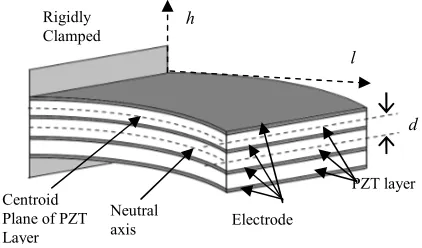
The free-standing multimorph structure is an extension of a previous study and the details of the fabrication process can be found in [10]. The main difference is that the PZT paste was printed and dried repeatedly for three cycles in order to achieve a thickness of 40 µm, before a layer of Ag/Pd of thickness 12 µm was printed on top of the dried PZT. The process was repeated to produce three laminar sections of PZT, separated by Ag/Pd electrodes to form a composite multimorph structure as shown in Fig.1.
All three sections of the laminar PZT were then polarized at the same time using a DC voltage source of 220 V (which is equivalent to an electric field strength of 5.5 MV/m) at 200 °C. Two polarization modes were investigated; series and parallel. A shaker was used to excite the multimorph samples at their resonant frequency, using a constant acceleration level of 50 m/s2. The electrical output from the samples was obtained by connecting their terminals in different configurations to identify the optimum method.
II. MULTIMORPH DESIGN
A multimorph structure, with one end rigidly clamped is shown in Fig. 1. When the structure resonates, an alternating voltage is produced as a consequence of piezoelectric d31
effect. At a point where the cantilever bends downward, tensile forces are induced on the upper piezoelectric element, thus generating a voltage of the same polarity as the poling voltage;
Free-Standing Thick-Film Piezoelectric
Multimorph Cantilevers for energy harvesting
Swee L. Kok, Neil M. White and Nick R. Harris
School of Electronics and Computer Science, University of Southampton,
Southampton SO17 1BJ, UK
1107 2
whereas the compressive forces on the lower piezoelectric element generate a voltage of opposite polarity to that of the poling voltage.
Fig. 1. Schematic diagram of a multimorph structure.
The output voltage of a piezoelectric cantilever can be estimated with the model developed by Roundy et al [11],
where Ain is the base input acceleration, ε is dielectric constant
of the piezoelectric material, ζT is the total damping ratio (the
sum of electrical and mechanical damping ratio), Cp is the
capacitance of the piezoelectric material and ET is the elastic
modulus of the composite structure.
One of the controllable factors that can be improved the output voltage is by increasing the distance between the PZT layer and the neutral axis of the multimorph structure, d. The d distance for a composite multimorph can be written as,
(
) (
)
and the elastic modular ratio was obtained from transformed-section method [12],Fabricated samples (Fig.2) of the dimensions shown in Table I were used to investigate the electrical output performance. The samples were polarized in series and parallel modes. In the series polarized sample, both the upper and lower PZT sections were polarized in the same direction toward the center section, creates an electrically neutral condition at the centre section, as shown in Fig. 3(a).
In the parallel polarized sample, the upper section and lower section of the PZT were polarized in an opposite direction, where one facing into and the other facing out from the center section which creates an opposite polarized centre section as shown in Fig. 3(b).
Fig. 2. (a) Fabricated samples and (b) Samples connected to terminals ready for polarization.
Fig. 3. Polarization in a (a) series and (b) parallel mode. The number beside each layer denotes the fabrication sequence of electrode layers.
1107 3
Device under test
Shaker
subsequently converted to a digital signal and is measured with National Instrument Sequence Test Program.
TABLE I
FABRICATED SAMPLE DIMENSIONS
Dimension Value (mm)
PZT Length 18
Electrode Length 17.5
PZT Width 9
Electrode Width 8.5
PZT Thickness 0.04
Electrode Thickness 0.012
Fig. 4. A free-standing multimorph sample mounted on a shaker
The electrical output from both the series and parallel polarized samples was obtained by connecting the electrode terminals in a configuration that resembles series, parallel and a combination between these two connections. For example, a connection between electrode number 1 and 2 is denoted as 1;2. A connection to make electrode number 2 and 4 as terminal positive (shorting 2 and 4) and electrode number 1 and 3 (shorting 1 and 3) as terminal negative denotes as 2+4; 1+3. The “;” denotes a separation between two terminals.
IV. EXPERIMENTAL RESULTS AND DISCUSSION
A series polarised sample with a configuration of 1;4 (short 2+3) produces an electrical output voltage of 1.3 V at load resistance of 38 kΩ, which is the sum of the voltage produced by the upper and lower PZT layer of 0.6 V (at 19.5 kΩ) and 0.74 V (at 19 kΩ) respectively, which is equivalent to a series connection of two resistive components of PZT. The output power of upper and lower PZT are around 22 µW and 30 µW respectively and the parallel configuration produced an output power of about 42 µW, as shown in Fig. 5.
In the ideal case, the upper and lower PZT layer produce an equal electrical output. In practice, however, the thickness of each layer of the film is not uniform because of fabrication tolerances and therefore the centroid of the PZT is not precisely coincident with the neutral axis. This creates a discrepancy of electrical output as discussed above.
Fig. 5 also shows that, when electrode 2 and 4 were connected as one terminal and, 1 and 2 as another terminal (2+4; 1+3), then a lower output power was generated at a lower optimum resistive load. This configuration is equivalent to a parallel connection of two resistive components of PZT.
Fig. 5. Output power as a function of resistive load for a series polarized sample.
Fig. 6. Output current-voltage for a series polarized sample.
Fig. 6 shows an output current-voltage relationship of the terminal connected configurations. Series configuration (1;4 short 2+3) produces the highest output voltage at a lower output current, while a parallel configuration produces the highest output current at a lower output voltage. A series configuration function as a voltage source for applications requiring a higher output voltage and it is preferable to switch to a parallel configuration for applications require a higher output current.
1107 4
configuration is actually equivalent to a combination of series and parallel configurations.
The maximum output voltage generated by a parallel polarised sample is lower than that generated from a series polarised sample as shown in Fig. 8. This shows that, a series polarized sample is suitable to be used as energy harvester, while a parallel polarized sample is suitable to be used as an actuator, which would produce a same deflection of cantilever with a lower input voltage from the converse piezoelectric effect.
Fig. 7. Output power as a function of resistive load for a parallel polarized sample.
Fig. 8. Output current-voltage for a parallel polarized sample.
V. CONCLUSION
The distance between the centroid of PZT to the neutral axis is one of the important factors in determining the electrical output for a free-standing cantilever structure. A free-standing multimorph structure offers two significant advantages over conventional piezoelectric cantilevers; one of which is its flexibility in fabrication and integration with microelectronic systems and the other one is the flexibility in switching between current and voltage source for energy harvesting applications. As expected from the experiment, a series polarized sample is suitable for use as an energy harvester, while a parallel polarized sample is preferred for actuator applications.
ACKNOWLEDGMENT
The PhD scholarship from Universiti Teknikal Malaysia Melaka is gratefully acknowledged.
REFERENCES
[1] N.M. White, P. Glynne-Jones, and S.P. Beeby, “A novel thick-film piezoelectric micro-generator,” Smart Mater. Struct, vol. 10, pp. 850-852, 2001.
[2] S.P. Beeby, R.N. Torah, M.J. Torah, P. Gynne-Jones, T. O’Donnell, C.R. Saha, et al, “A micro electromagnetic generator for vibration energy harvesting,” Journal of Micromechanics and Microengineering, vol. 17(7), pp. 1257-65, 2007.
[3] P.D. Mitcheson, P. Miao, B.H. Stark, E.M. Yeatman, A.S. Holmes, and T.C. Green, “MEMS electrostatic micropower generator for low frequency operation,” Sensor and Actuators A: Physical, vol. 115(2-3), pp. 523-9, 2004.
[4] H.A. Sodano, D.J. Inman, and G. Park, “Comparison of piezoelectric energy harvesting devices for recharging batteries,” Journal of Materials Science: Materials in Electronics, vol. 16, pp. 799-807, 2005.
[5] S. Roundy, P.K. Wright, and J. Rabaey, “A study of low level vibrations as a power source for wireless sensor nodes,” Computer communications, vol. 26, pp. 1131-44, 2003.
[6] Y.B. Jeon, R. Sood, J. Jeong, and S.G. Kim, “MEMS power generator with transverse mode thin film PZT,” Sensor and Actuators A, vol. 122, pp. 16-22, 2005.
[7] F. Yalcinkaya, and E.T. Powner, “Intelligent structures,” Sensor Review, vol. 16, pp. 32-7, 1996.
[8] R. Torah, S.P. Beeby, N.M. White, “An improved thick-film piezoelectric material by powder blending and enhanced processing parameters,” IEEE Trans. Ultrason. Ferroelectri. Freq. Control, vol. 52(1), pp. 10-6, 2005.
[9] H. Birol, T. Maeder, and P. Ryser, “Application of graphite-based sacrificial layers for fabrication of LTCC (low temperature co-fired ceramic) membranes and micro-channels,” Journal of Micromechanics and Microengineering, vol. 17(1), pp. 50-60, 2007.
[10] S.L. Kok, N.M. White, and N.R. Harris, “Free-standing thick-film piezoelectric device,” Electronics Letters, vol. 44(4), pp. 280-1, 2008. [11] S. Roundy, and P.K. Wright, “A piezoelectric vibration based generator
for wireless electronics,” Smart Materials and Structures, IOP, vol. 12, pp. 1131-42, 2004.