DOI: 10.12928/TELKOMNIKA.v14i4.4164 1351
Optically Switched Frequency for Reconfigurable
Dipole Antenna Using Photodiode Switches
Erna Risfaula Kusumawati1, Yono Hadi Pramono2, Agus Rubiyanto3 Physics Department, Faculty of Mathematics and Natural Science, Sepuluh Nopember Institute of Technology, Surabaya (ITS), Indonesia *Corresponding author, e-mail: [email protected], [email protected],
Abstract
The design, fabrication, and measurement of reconfigurable antenna using photodiode switches have been investigated. The antenna had dimension 104 mm x 41 mm x 1.6 mm and FR4 substrate with relative permittivity 4.8. It structure was Coplanar Stripline (CPS) dipole. Two photodiodes had assembled on gap in both dipole arms, which was activated by 650 nm red laser. There was shifting frequency and return loss at under illuminated by laser. The experimentally and theoretically result for the proposed reconfigurable antenna are having a good agreement with large frequency shifting. The fabricated antenna was easily fabricated, simple structure, and possible to realize in many application of Wi-fi communication which using optical switching.
Keywords: CPS, dipole, frequency shifting, optical switching, photodiode, reconfigurableantenna
Copyright © 2016 Universitas Ahmad Dahlan. All rights reserved.
1. Introduction
Antenna is a basic component in communication system. It is very important and needed in communication system, specifically wireless communication system which has been running remarkably and dynamic. It causes the increase demand of antennas. Communication system which is generally complex needs antennas which have advance capabilities and good performances. So, many researchers have conducted experiments attempting to improve capabilities and performances of antenna in order to meet the need of communication system which grows continuously.
One type of antenna which is able to accommodate the change of communication system necessity is reconfigurable antenna [1]. Such an antenna is able to adjust with the necessity of the communication system. In some ways it can convert operating frequency, radiation pattern, impedance, bandwidth via shorting/reactive loading to require resonant mode switching, by moving part (mechanical reconfiguration), optical switching, electronic switching, and feed network switching. Due to the fact that reconfigurable antenna adjustable, this antenna can eliminate the need of multiple antenna for communication systems.
2. Optical Switches
The switching device is used on this paper is photodiode. Photodiode is one of kind of semiconductor device which has ability to change photon (light) into electric current [18]. When the light has certain wavelength on the photodiode, it is absorbed. Then, the photon energy is distributed to valence electron and enhances them to the conduction gap. This process awakes electron-hole pairs which called photo carrier. Photo carrier is produced in depletion region. The high electric field arise on depletion region will develop photocurrent on photodiode. The use of photodiode as optical switching in transmission line is based on the characteristic difference between photodiode that is illuminated by light and unilluminated. When it is illuminated by light, photodiode that is located on gap of transmission line will acts as short circuit. The photodiode act as a bridge is connecting one of the transmission line parts to others. This condition causes an increase of electrical length of transmission line, lowering the impedance of transmission line. On the other hand, on unilluminated photodiode, it acts as open circuit and the transmission line impedance is high [19]. The change in electrical length is closely related with the operating frequency of transmission line as is given by Equation (1) and (2) [20]. For operating frequency in unilluminated state (OFF-state) is given by [21-23], meanwhile in illuminated state (ON-state) is given by Equation (4).
0
From Equation (3) and (4), we can define shifting of frequency as:
off on
= effective dielectric constantf
= frequency shifting
= electrical length of transmission linel
= physical length of transmission lineoff
f
= antenna frequency on unilluminated(off-state)on
f
= antenna frequency on illuminated (on-state) c = velocity in free space3. Research Method
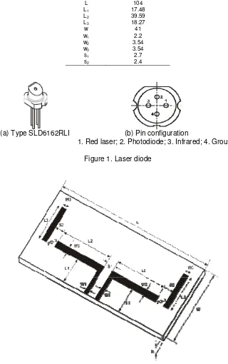
Antenna design is a balanced dipole in CPS (Coplanar Stripline) fabricated on fiber substrate with permittivity of 4.8 and 1.6 mm thick. The dimension of the substrate is 104 mm × 41 mm×1.6 mm. The antenna was equipped with two photodiodes PD-1 and PD-2 as photoconductive switching. The input matching impedance (Z0) is 50 Ohm according to impedance from connector. Figure 1 shows the photodiode GaAs type SLD6162RLI. The photodiode characteristics are presented by [24]. The antenna is designed in the form of planar structures. The fabricated antenna design is given by Figure 2 with the fixed parameter size on Table 1.
Table 1. Dimension of Fabricated Antenna
Parameter Size (mm) L 104
L1 17.48
L2 39.59
L3 18.27
w 41
w1 2.2
w2 3.54
w3 3.54
s1 2.7
s2 2.4
(a) Type SLD6162RLI (b) Pin configuration
1. Red laser; 2. Photodiode; 3. Infrared; 4. Ground
Figure 1. Laser diode
3. Results and Discussion
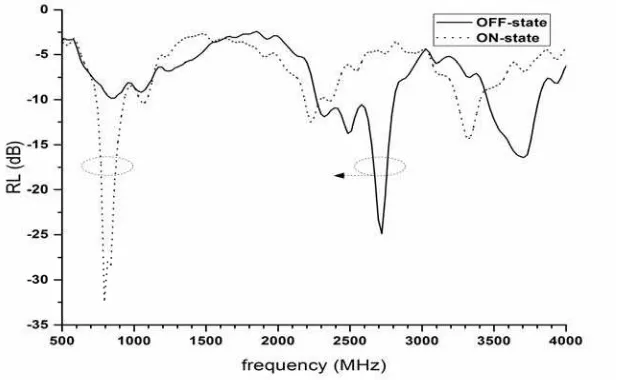
The characteristic result of antenna is measured by using a Network Analyzer in “OFF-state” and “ON-“OFF-state”. OFF-state is dark or unilluminated condition. ON-state is illuminated by red laser with 650 nm wavelength.The measurements are also conducted in chamber to eliminate noise. Figure 3 shows the return loss responds to frequencies.
Figure 3. Graph resonant frequency with return loss of fabricated antenna
If RL value -17 dB set as threshold (similar low pass filter), the resonance frequency of fabricated antenna 2720 MHz in OFF-state and 800 MHz in ON-state. It shows that resonance frequency of antenna shifts 1920 MHz. Theoritically, 1942 MHz frequency shifting calculated by using Equation (6) with
= 3.5 which
value obtained from the graph ratio of photocurrent to dark current for GaAs photodiode [24]. If the frequency shifting from measurement result is compared with theoretically calculation, it shows nearly equal value. However, if frequency shifting is compared with other researches, it shows significant result. As the research conducted by Kiriazi et al. [6], showed that the antenna that switched by using RF-MEMS operate in dual frequencies and have shifting frequencies 20 MHz for first frequency and 260 MHz for second frequency. In another research [7], where the antenna switched by using varactor diode, achieve dual frequency shifting 357 and 126 MHz.4. Conclusion
The design, fabrication, and measurement of reconfigurable CPS dipole antenna using photodiode switches have been presented. The experimentally and theoretically result for the fabricated reconfigurable antenna are having a good agreement with large frequency shifting. The proposed antenna would make it possible to realize in many application of Wi-fi communication which using optical switching.
Acknowledgements
This work was supported by Ministry of Research, Technology and Higher Education of the Republic of Indonesia.
References
[1] Bernhard JT. Reconfigurable Antenna. Urbana–Champaign: Morgan & Claypool. 2007: 1-2.
[3] Panagamuwa CJ, Chauraya A, Vardaxoglou JC. Frequency and Beam Reconfigurable Antenna Using Photoconducting Switches. IEEE Transactions on Antenna and Propagation. 2006; 54(2): 449-454.
[4] Tawk Y, Albrecht AR, Hemmady S, Balakrishnan G, Christodoulou CG. Optically Pumped Reconfigurable Antena Systems (OPRAS). IEEE Antennas and Propagation Society International Symposium. Toronto. 2010: 1-4.
[5] Liu D, Charette D, Bergeron M, Karwacki H, Adams S, Lanning B, Kustas F. Structurally Embedded Photoconductive Silicon Bowtie Antenna. IEEE Photonics Technology Letters. 1998; 10(5): 716-718. [6] Kiriazi J, Ghalie H, Radaie H & Haddara H. Reconfigurable Dual-Band Dipole Antenna on Silicon
Using Series MEMS Switches. Proceedings of the IEEE/URSI International Symposium on Antenna and Propagation. Columbus. 2003; 1: 403-406.
[7] Shynu SV, Augustin G, Aananda CK, Mohanan P & Vasudevan K. Design of Compact Reconfigurable Dual Frequency Microstrip Antennas Using Varactor Diodes. Progress in Electromagnetics Research (PIER). 2006; 60: 197-205.
[8] Razali AR, Abbosh AM, Antoniades MA. Compact Planar Multiband Antennas for Mobile Applications. Croatia: InTech. 2013: 86-89.
[9] Sung Y. A Switchable Microstrip Patch Antenna for Dual Frequency Operation. ETRI Journal. 2008; 30(4): 603-605.
[10] Romano N. Design of A Reconfigurable Antenna for Ground Penetrating Radar Applications.
Progress in Electromagnetics Research (PIER). 2009; 94: 1-18.
[11] Kang W, Ko KH, Kim K. ACompact Beam Reconfigurable Antenna for Symmetric Beam Switching.
Progress in Electromagnetics Research (PIER). 2012; 129: 1-16.
[12] Peroulis D, Sarabandi K, Katehi L. Design of Reconfigurable Slot Antennas. IEEE Transactions on Antennas and Propagation. 2005; 53(2): 645-654.
[13] Gupta KC, Li J, Ramadoss R, Wang C. Design of Frequency-Reconfigurable Rectangular Slot Ring Antennas. Antennas and Propagation Society International Symposium IEEE. Salt Lake City. 2000; 1: 326.
[14] Fortaki TD, Benkouda S, Amir M, Benghalia M. Air Gap Tuning Effect on the Resonant Frequency and Half-power Bandwidth of Superconducting Microstrip Patch. PIERS online. 2009; 5(4): 350-354. [15] Ningsih YK, Hadinegoro R. Low Mutual Coupling Dualband MIMO Microstrip Antenna Parasitic with
Air Gap. TELKOMNIKA Telecommunication Computing Electronics and Control. 2014; 12(2): 405-410.
[16] Kusumawati ER, Pramono YH, Rubiyanto A. Reconfigurable Dipole Microstrip Antenna using Solar Cell as Substrate Controlled by Optical Source.Proceeding of 3rdMakassar International Conference on Electrical Engineering and Informatics (MICEEI). Makassar. 2012; 3: 221-224.
[17] Kusumawati ER, Pramono YH, Rubiyanto A. Design and Fabrication of Tunable Microstrip Antenna using Photodiode as Optical Switching Controlled by Infrared. Communication Network and Satellite (COMNETSAT) IEEE International Conference. Yogyakarta. 2013: 55-58.
[18] Saleh BEA, Teich MC. Fundamental of Photonics. New York: John Wiley & Sons. 1991: 657- 665. [19] Kumar G, Ray KP. Broadband Microstrip Antennas. Boston: Artech House. 2003: 262-263.
[20] Edwards TC, Steer MB. Foundations Of Interconnect and Microstrip Design. 3rded. New York: John Wiley & Sons. 2000: 90.
[21] Balanis CA, Antenna. 2nd. New York: John Wiley & Sons. 1997: 729.
[22] Darsono M, Wijaya E. Circularly Proximity-Fed Microstrip Array Antenna for Micro Satellite.
TELKOMNIKA Telecommunication Computing Electronics and Control. 2013; 11(4): 803-810. [23] Zainol N, Zakaria Z, Abu M & Yunus MM. Harmonic Suppression Rectangular Patch Antenna with
Circularly Polarized. TELKOMNIKA Telecommunication Computing Electronics and Control. 2016; 14(2): 471-477.
[24] Liu X, Li M, Chen Z, Jia G, Bian T & Li Y. Photo-and-Dark-Current-Voltage Characteristics of Normal-Incidence GaAs Photodetectors With Two Types of Electrode Configurations. Proceedings of SPIE,