ISSN: 1693-6930
accredited by DGHE (DIKTI), Decree No: 51/Dikti/Kep/2010 377
Low-Cost Based Eye Tracking and Eye Gaze Estimation
I Ketut Gede Darma Putra*1, Agung Cahyawan2, Yandi Perdana3 Departement of information technology and Electrical Engineering, Udayana University
Bukit Jimbaran, Bali, Indonesia, phone +62361703315
e-mail: [email protected]*1,[email protected], [email protected]
Abstrak
Harga dari sistem penjejak gaze untuk penggunaan masyarakat umum masih sangat mahal. Alasan utama mahalnya sistem penjejak gaze adalah karena kamera dan lensa yang digunakan untuk membuatnya berkualitas tinggi dan tingginya biaya pengembangan. Penelitian ini membangun sistem penjejak gaze berbiaya rendah. Alat dibuat dengan melakukan modifikasi pada kamera web agar bekerja dalam spektrum infrared. Teknik baru juga diperkenalkan disini untuk mendeteksi koordinat pusat pupil menggunakan connected component labeling. Dengan mengkombinasikan teknik tersebut dengan regresi polinomial orde 3 dalam proses kalibrasi untuk menentukan titik gaze. Hasil pengujian menunjukkan sistem ini mampu memberikan akurasi yang dapat diterima dengan galat piksesl 0.39o dalam derajat visual.
Kata kunci: connected component labeling, penjejak gaze, infrared, kamera web, regresi polinomial
Abstract
The costs of current gaze tracking systems remain too high for general public use. The main reason for this is the cost of parts, especially high-quality cameras and lenses and cost development. This research build the low cost based for gaze tracking system. The device is built by utilizing of modified web camera in infrared spectrum. A new technique is also proposed here in order to detect the center pupil coordinate based on connected component labeling. By combination the pupils coordinate detection method with third order polynomial regression in calibration process to determine the gaze point. The experiment results show our system has an acceptable accuracy rate with error pixel 0.39o in visual degree.
Keywords: webcam, infrared, gaze tracking, connected component labeling, polynomial regression.
1. Introduction
Gaze tracking has been used for many decades as a tool to study human cognitive process including reading, driving, watching commercials, and other activities [1]. With the advent of personal computers, potential integration of such systems has been considered only recently in 1991 [2]. Successful attempts to employ gaze tracking as user interface were made to allow users with movement disabilities to type by looking at virtual keyboard [3], or for mouse pointer control [4]. Systems of this kind have also been used by individuals without any disabilities to enhance performance [5],[6]. In recent years, gaze tracking is widely used in the areas of intelligent control [7], virtual reality, video games, robotics, human computer interaction, eye diseases diagnosis, human behavior studies, etc [8]. Lee et al used gaze tracking system for controlling IPTV [9].
Gaze Tracking system detect the eye location in image and estimate the gaze path by measurement of point of gaze (POG). The eye position is commonly measured using the pupil or iris center. The detected eyes in the images are used to estimate and track where a person is looking in 3D or alternatively determining the 3D line of sight [10]. Gaze tracking system is divided into head mounted or wearable-camera-based or intrusive system which required direct contact with the eye, as in [11],[12] and head-free or remote based or nonintrusive system which avoid any physical contact with the user as in [13],[14],[15].
cameras and lenses, the cost relatively low cost systems ha The design work des modern, low-cost systems. T design of hardware, in this c point. The vantage point can b away, as in a device on a tabl mounted camera, as will be d of the user’s pupil within the i are passed through a speciali displayed in front of the user. looking on the display. This cr the user is looking on the scre
2. Research Method
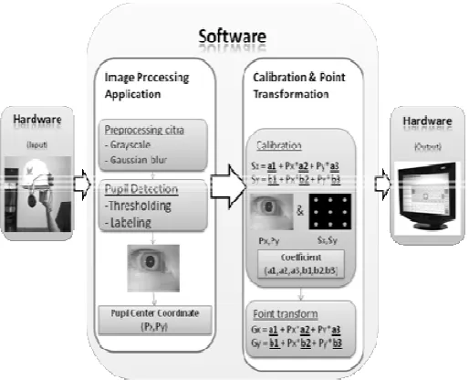
2.1. General System Overvie In general the system in Figure 1. The first module is have worked in infrared spec and tracked.
Fig
The second module is softwa pupil coordinate using thresho coordinate to monitor coordin polinomial regression, and the pixel between gaze coordina coordinate.
st of development, and the relatively small market [ have been investigated as in [17],[18].
escribed herein shows the accuracy that can b . The three most significant contributions of this case a webcam [19] for worked in the infrared t labeling algorithm to detect the pupil in the in the visible spectrum, and use of higher dimension
ted gaze position to the position on the computer s system, images of the eye are taken by a camer his image data is a picture of the user’s eye from a n be close to the user’s eye, as in a head mounted ble near the user. For this project, the design team discussed later. The image is processed to deter e image. The coordinates of the detected center o ialized set of algorithms to accurately position a cu er. The cursor position on the screen represents w creates an open loop tracking system where a cur
reen.
view
m is built in this research consist of two main mod is hardware design, which is modification of the w ectrum in such way so that the pupil relative easi
Figure 1. General overview of the system
are design, which is the main purpose are for det holding and connected component labeling algorith dinate through calibration and point transformatio the last is testing process to measure accuration ra
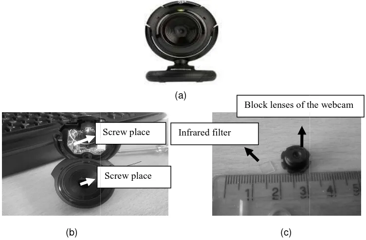
2.2. Hardware Design The hardware design 1. Infrared filter removal
Every webcam in gen allowing visible light. Because webcam must be modified to useful for eye trackers, mainly for controlling light conditio estimation [8].
(b)
Figure 2. Infrared filter remov scre
2. Attachment of visible light f The next process is to the webcam as shown in Figu black part of that film, usually to block the visible light is ver purposes of this research is t cost component.
3. Making of infrared light sou After the webcam has for the webcam. In this rese connected into 2 battery each infrared LED. This research u close with the eye, so 1 LED is
4. Finalizing
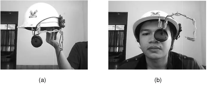
The last step to design as shown in Figure 5. This hel
n of this system consist of 4 main process :
eneral equipped with infrared filter for blocking the se in this research will use infrared spectrum app to remove the infrared filter as shown in Figure 2 nly because it is not only invisible to the user but al itions, obtaining higher contrast images, and
(a)
(c)
oval, (a) Webcam Microsoft Lifecam VX-1000, (b) W crew is closed, (c) Infrared filter is removed
t filter
s to attach a filter to block visible light and let only igure 3. The filter is film negative already to be prin lly in the beginning and the end of roll film. Price o very expensive, so film negative is used instead, b s to built eye tracking and eye gaze tracking syste
ource
as been modified, the next step is supplies the inf esearch infrared light source is built using 1 infr
ch of them 1.5 volt, resistor 33 ohm, and 1 switch to use only 1 LED after consider that webcam will b
is enough for infrared source.
ign hardware is linking up together all the compone elmet later will have weared by the users of the sys
Block lenses of th
Infrared filter Screw place
Screw place
he infrared light and proach, so that the e 2. Infrared light is also it can be used d stabilizing gaze
) Webcam after the
ly infrared light into rinted and take the of the original filter , because the main stem based on low
infrared light source infrared LED which to turn on or off the ll be positioned very
nents in a helmet system.
(a)
Figure 3. Attachment of visib
Figure 4
(a)
Figure 5. (a
2.3. Software Design There are two main application, which processes calibration and point transfo coordinate of the eye pupil to 1 infr 33 oh
1 switch to turn on or off LED
2 battery each of 1.5 volt
(b)
isible light filter, (a) film negative, (b) Attachment of block visible light
4. Infrared LED, resistor, switch and batteries
(b)
(a) Final hardware, (b) hardware weared by user
in subsystems to the software. The first is the im s the image and locates the center of the pupil. T sformation subsystems, which do the mapping to the screen coordinate. The software is develope
Attachment of film negative
nfrared LED and 1 resistor ohm
off the of them
of film negative to
C++ and OpenCV library. The the following sections.
2.3.1. Detection of the cent The pupil may be dar contrast is sufficiently large. Y algorithm to locate the pupils constraints using a skin-color model and it will fail in the pre Yang et al applied the ellipse coordinates of pupil edge pixe This research use simple tec labeling.
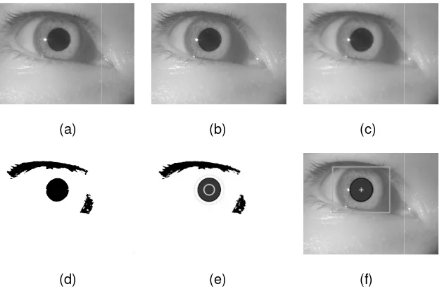
The steps to detect th begins by capturing a eye ima grayscaling process convert th smoothed using Gaussian filt reduce sharp edges, aiding th
(a)
(d)
Figure 6. Detection of the cen (c) Gaussian blur image, (d
The next step is thresholding clearly visible as a black c Thus, the system selects the center coordinate of this conne
he intricacies of these subsystems will be described
enter coordinate of the pupil
arker than their surroundings and thresholds may . Yang et al and Stiefilhagen at al introduce an i ils by looking for two dark regions that satisfy certa lor model. Their method is limited by the results
resence of other dark regions such as eyebrows a se fitting algorithm to fit a standard ellipse or cir ixels. The center of the ellipse or circle is the cente technique to detect the pupil center using conne
the center of pupil is used here are shown in Figur mage frame from the camera via OpenCV’s camera t the RGB color to gray color space. After that the g
filter to remove any noise in image. The smooth the pupil detection system.
(b) (c)
(e) (f)
center of pupil, (a) capture frame from camera, (b) g (d) binary image, (e) component labelling image, (f
g the smoothed image to obtain the binary image. component in this image. However, there may represent areas of the image of almost exactly the
nnected component labeling step exists here to and determine which is representative of the pu group of pixels with values within a certain range m used is an open source add-on for OpenCV. d component have been located, the system c uch as area, aspect ratio, roundness, and more. T tally determined values for a pupil and connected Due to the nature of the human eye and surroundin
e connected component that fits all parameters f e correct connected component. The algorithm th nnected component.
ed in more detail in
2.3.2. Calibration and Poin Calibration is necess rectangle while the human ey center of the pupil to the coo system is restarted due to var the screen every time the sam shapes will require a new cal 16, or 25 pixel locations, by a [8], [20], [21]. This paper used (equation (5) and (6)) order eye is not. Mapping is required to transform the c oordinates on the display. Calibration must be don variations in use. The eye will not be in the same lo ame user wears it, also, different users with differ alibration. In this research, the calibration process y asking the user to ‘look at the dot’ in monitor. Th
(b) (c)
ration pixel locations, (a) 9 pixel, (b) 16 pixel, (c) 25
location of the eye when looking at those known p n equation are determined using polynomial regre ed first (equation (1) and (2)), second (equation (3) der polynomial regression. Polynomial regression
ate correlation of variables. Shown below the polyn
2 ∗ 3
ents center pupil coordinate and target (screen mo 25 points sample/training points in the monitor will
this (1), (2), (3), (4), 5) and (6) equations. To o uare method. This method will convert the equatio n sample for first order polynomial from equation 1 a
regression coefficients are calculated using Gauss Elimination methods. The next step after the coefficients are obtained is transform or mapping the pupil coordinate to screen coordinate to get the gaze point (Gx,Gy). This point can be achieved by multiplication of pupil coordinate output from detection of center pupil with regression coefficients output from calibration process. The first (equation (9) and (10)), second (equation (11) and (12)), and third (equation (13) and (14)) order polynomial gaze point can be computed as below:
Gx = KoefX[0] + Px ∗ KoefX[1] + Py ∗ KoefX[2] (9)
This gaze point can be used to control the movement of mouse cursor using our eye.
3. Results and Analysis
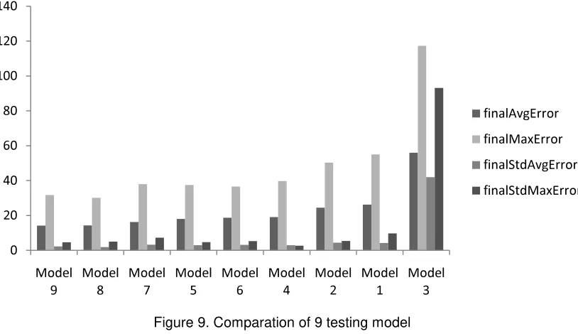
To obtain performance of this system, the testing used data from 10 users. Each user do 9 model testing (combination of 9, 16, 25 sampel point with first, second and third order polynomial). From each model testing of each user is calculated the gaze points and calculate the distance (error pixels) between the point and 36 testing points in the monitor screen using euclidean distance [22] (see Figure 8). Average (avgError) and maximal (maxError) error distance from 36 distances from each model testing of each user are computed. To measure which model has the best performance, four indicators below are computed using 10 users in offline mode:
- average distance/error pixel (finalAvgError)
- average maximal distance/error pixel (finalMaxError)
- standard deviation between avgError and finalAvgError (finalStdDeviasiAvgError) - standard deviation between MaxError and finalMaxError (finalStdDeviasiMaxError).
(a)
Figure 8. (a) 36 point testing
Fig
The graphic is shown left to right. Sorting process u The graphic tell us several thin 1. In general all models exce result. This accuracy rang This result relatively close 2. The best model from left to 3. Model that use more sam This can been seen from model after that are mode
ing grid, (b) testing result from combination of 25 sa third order regression polynomial.
Figure 9. Comparation of 9 testing model
wn in Figure 9 has been sorted based on the lowe s uses average value from 4 indicator which has hings below:
xcept model 3 give a high enough accuracy based nge from 26.2 until 14.2 pixel or 0.73o until 0.39o
order polynomial (non linier) regression give mo ion (first order). This can been seen from the top th nd 8 uses third and second order respectively, wh
ree model 5, 6 and 4, in model 5 and 6 uses third a odel 4 uses first order. There was exception in nex
and 3, in model 3 which uses third order give the worst accuracy, this is because the number of sample points uses in model 3 are 9 points which is that sample points smaller than the number of regression coefficients result uses third order (10 coefficients). Main prerequisite from polynomial regression method is the number of sample points has to be greater than the number of regression coefficients result.
5. Choise of number of order in polynomial regression has direct effect to the number of sample points in calibration process. The higher order is used, so the greater number of sample points is required.
4. Conclusion
We have been developed a low cost device for gaze tracking system. The device is built by utilizing of modified webcam in infrared spectrum. A new technique is proposed in this paper to detect the center pupil coordinate based on connected component labeling. The first, second, and third polynomial regression also tried in the experiments to determine the point of gaze. By combination of center pupil coordinate detection method with third order polynomial regression in determining the gaze point, the experiment results show our system has an acceptable accuracy rate with error pixel range between 26.2 to 14.2 pixel or 0.70 o to 0.39o in visual degree. The applied of this system on specific application for general public domain is interesting further research area.
References
[1] A. Duchowski. A breadth-first survey of eye-tracking applications. Behavior Research Methods Instruments and Computers. 2002; 34(4): 455–470.
[2] R. Jacob. The use of eye movements in human-computer interaction techniques: what you look at is what you get. ACM Transactions on Information Systems. 1991; 9(2): 152–169.
[3] P. Majaranta, K. Raiha. Twenty years of eye typing: systems and design issues. In ACM Eye Tracking Research and Applications Symposium. New Orleans, Louisiana, USA. March 2002; 1: 15–22.
[4] A. J. Hornof, A. Cavender, R. Hoselton. Eyedraw: a system for drawing pictureswith eye movements. In ACM SIGACCESS Conference on Computers and Accessibility. Atlanta, Georgia. October 2004; 1: 86–93.
[5] L. Sibert, R. Jacob. Evaluation of eye gaze interaction. In SIGCHI Conference on Human Factors in Computing Systems. Hague, Netherlands. April 2000; 1: 281–288.
[6] V. Tanriverdi, R. Jacob. Interacting with eye movements in virtual environments. In Proceedings of the SIGCHI Conference on Human Factors in Computing Systems. Hague, Netherlands. April 2000; 1: 265–272.
[7] Yang X, Jiande Sun, Ju Liu, Jinyu Chu, Wei Lie, Yuling Gao. A Gaze tracking scheme for eye-based intelligent control. Proceedings of the 8th world Congress on Intelligent Control and Automation. Jinan, China. July 2010; 1: 50-55.
[8] Jose Sigut, Sid-Ahmed Sidha. Iris Center Corneal Reflection Method for Gaze Tracking Using Visible Light. IEEE Transaction on Biomedical Engineering. 2011; 58(2): 411-419.
[9] Lee HC., Due Thien Luong, Chul Woo Cho, Eui Chul Lee, Kang Ryoung Park. Gaze Tracking system at a distance for controlling IPTV. IEEE Transaction on Consumer Electronics. 2010; 56(4): 2577-2583.
[10] Dan Witzner Hansen, Qiang Ji. In the Eye of the Beholder: A Survey of Models for Eyes and Gaze. IEEE Transaction on Pattern Analysis and Machine Intelligence. 2010; 32(3): 478-500.
[11] Lawrence H.Yu, Moshe Eizenman. A New Methodology for Determining Point-of-Gaze in Head-Mounted Eye Tracking Systems. IEEE Transactions on Biomedical Engineering. 2004; 51(10): 1765-1773.
[12] Zhor Ramdane Cherif, Amine Nait Ali. An Adaptive Algorithm for Eye-Gaze-Tracking-Device Calibration. IEEE Transactions On Instrumentation and Measurement. 2008; 57(4): 716-723. [13] Craig Hennessey, Borna Noureddin, Peter Lawrence. Fixation Precision in High-Spreed Noncontact
Exe-Gaze Tracking. IEEE Transactions on systems, Man, and cybernetics-Part B:Cybernetics. 2008; 38(2): 289-298.
[14] Craig Hennessey, Peter Lawrence. Noncontact Binocular Eye-Gaze Tracking for Point-of-Gaze Estimation in Three Dimensions. IEEE transactions on biomedical engineering. 2009; 56(3): 790:799.
[16] L. Young, D. Sheena. Survey of eye movement recording methods. Behavior Research Methods and Instrumentation. 1975; 7: 397–429.
[17] J.Babcock, J.Pelz. Building a light weight eye tracking head gear. In ACM Eye Tracking Research and Applications Symposium. San Antonio, TX, USA. 2004; 1: 109–114,
[18] Li, Donheng, Babcock Jason, J Parkhurst Derrick. openEyes: a low-cost head-mounted eye-tracking solution. ACM Eye Tracking Research and Applications Symposium. San Diego, CA, USA. 2006; 1: 95-100.
[19] Kartika Firdausy, Selamat Riyadi, Tole Sutikto, Muchlas. Aplikasi Webcam untuk Sistem Pemantau ruang berbasis Web. TELKOMNIKA. April 2008; 6(1): 39-48.
[20] Goujian Shao, Ming Che, Bingyi Zhang, Kunfang Cen, Wei Gao. A Novel Simple 2D Model of Eye Gaze Estimation. Second International Conference on Intelligent Human-Machine Systems and Cybernetics. Nanjing, China. 2010; 1: 300-304.
[21] Qiong Zhang, Zhiliang Wang, Jiannan Chi, Pengyi Zhang, Yi Yang. Design and Calibration for Gaze Tracking System. 2nd IEEE international conference on information management and engineering. Chengdu, Sichuan, China. April 2010; 5: 221-225.