International Journal of Applied Engineering Research ISSN 0973-4562 Volume 11, Number 15 (2016) pp 8432-8435 © Research India Publications. http://www.ripublication.com
8432
Atmega16 Implementation As Indicators Of Maximum Speed
1
Anna Nur Nazilah Chamim, 2Didik Ahmadi, 3Iswanto
1
Department of Electrical Engineering, Universitas Muhammadiyah Yogyakarta E-mail: [email protected], [email protected],id
Abstract
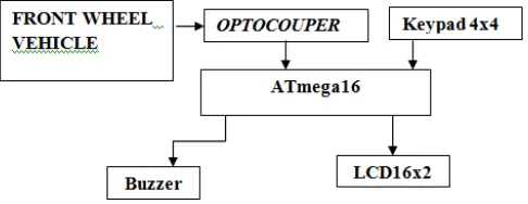
Motorcycle accidents caused by sudden deceleration or exceed maximum safe speed of vehicles are still common. There is no tool that can provide alerts when the speed has exceeded the safe speed limit for vehicles allowed. Hence, the study aims to design and manufacture implementation of ATmega16 as an indicator of the maximum speed. Output data is obtained in the form of increasing speed. Maximum speed indicator system consists of atmega 16 as the main processing unit, sensor optocoupler, 4x4 keypad, buzzer and LCD LM162. It includes the output of the transducer which is processed by a microcontroller keypad which is then forwarded to the buzzer and LCD LMB162. Testing is conducted by direct tests on the vehicle running, and the obtained results show the maximum speed indicator device made to work properly and in accordance with the specifications of the predetermined design, so that it can give a warning when the safe speed is being and has been exceeded.
Keywords: Microcontroller, Indicators, Maximum speed, Motorcycles, Vehicle accident
INTRODUCTION
Each vehicle has different characteristics particularly two-wheeled vehicles. At first the characteristics of two-two-wheeled vehicles with the same type of products are the same. But having reached the users, the characteristics are changing because they adapt to the characteristics of the users. The characteristics of the vehicle affects the safe speed that can be achieved. Safe speed is the speed that is considered safe frequently caused by a rider who did sudden deceleration, and because it exceeds the maximum safe speed for the vehicle. A tool that can be used as speed indicators and may give a warning when the speed has exceeded the safe speed limit allowed for vehicles is needed to reduce and avoid accidents caused by speeds exceeding the safe speed limit. Some previous researchers have conducted researches on measuring speed included Rajab et al. [1] using piezoelectric to measure the speed of a vehicle. Some other researchers such as Zhang et al. [2] used sensor less speed to measure BLDC motor speed.
The other researchers applied microcontroller and FPGA to measure the speed of the motor. Millan-Almaraz et al. [3] used FPGA control to measure the speed of the motor with wavelet algorithm. In addition to using FPGA, the other
researchers such as Nadh & Praba [4] used PIC microcontroller to remotely monitor the speed of an induction motor while using zig bee and SMS to transmit speed data. PIC microcontroller was also used by Isik et al. [5] to monitor the motor speed of permanent magnet DC (PMDC). The motor speed data were monitored and plotted by using fuzzy algorithms.
Fuzzy algorithm is an artificial intelligence algorithm used to control a system such as quadrotor [6],[7] and to create path planning as practiced by Iswanto et al. [8],[9] applying fuzzy path planning on a quadrotor. In artificial intelligence system, the algorithm was also used by Tunggal et al.[10] to detect the heart rate.
This paper presents fuzzy algorithm applied to the microcontroller used to monitor the speed of a motor cycle. With the algorithm, the microcontroller can calculate the speed of the motorcycle and give a warning if the speed used exceeding the maximum speed limit.
RESEARCH METHOD
Model of safe speed indicator system design is a design model that is a scheme of the modules making up the block devices, so it will be on to the system at a plant in the form of safe speed indicator devices.
Figure 1: Block diagram of system
International Journal of Applied Engineering Research ISSN 0973-4562 Volume 11, Number 15 (2016) pp 8432-8435 © Research India Publications. http://www.ripublication.com
8433 Figure 2: Schematic circuit
To facilitate the testing tool and isolate the failure possibilities in making circuits, circuit system is printed into several modules, namely:
ATmega16 Microcontroller Module.
The series of microcontrollers used in calculating the system consist of a minimum system microcontroller ATmega16. The ATmega16 microcontroller minimum system consists of a 12 MHz crystal and two 33pF capacitors to support the internal oscillator circuit. Microcontroller minimum system also features power on reset circuit that occurs when the system is turned on. Power on reset circuit consists of a single 10 kΩ resistor and a 10μF/16V electrolyte capacitor.
Figure 3: Minimum circuit ATmega16
4x4 keypad module.
The series serve as a keypad for input of the microcontroller [12]. This module consists of 16 push-buttons arranged in a matrix. The way this module work is that when one of the push button is pressed, the microcontroller ATmega16 will obtain information such as the number of columns and row
buttons pressed which then represents as a particular function key.
Figure 4: circuit 4x4 keypad
Optocoupler Sensor.
Optocoupler is a device that consists of two parts: a transmitter and a receiver, in which the detection is between the light source and light receiver. The series serve as a counter optocoupler spinning wheel. Optocopler output of the sensor will be submitted to the microcontroller interrupt pin. This module contains the components required by the sensor support including resistors and capacitors. The way of this sensor work is when the front wheel motor rotates 360°, sensor detects the color changes from dark to light and gives the output of a voltage of 5 volts.
Figure 5: Optocoupler Sensor circuit
LCD Module LMB16x2.
International Journal of Applied Engineering Research ISSN 0973-4562 Volume 11, Number 15 (2016) pp 8432-8435 © Research India Publications. http://www.ripublication.com
8434 LCD driver can display alphanumeric characters, Japanese characters (katakana), and some symbols. The controller contains a ROM-forming character (character generator ROM) size 9920 bits generate 240 characters consisting of 208 characters with a resolution of 5x8 dot (dot, pixel) and 32 characters with 5x10 dots. The controller also contains a character-forming RAM that can store 64 characters 8 bits.
Figure 6: LCD series LMB16x2
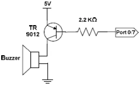
BUZZER Module.
This tool serves as buzzer audible indicator or marker when the vehicle is exceeding the speed limit. Buzzer [14] is connected to the microcontroller port which is the circuit using a buzzer C9012 transistor type. Basically buzzer is connected to Vcc voltage of 5 volts and then switched by using a transistor. So that the sound of the buzzer depends on the condition of the transistor at the time. If the transistor is ON (due to low flows on the basis, with the provision of logic '0'), the buzzer gets Vcc voltage, but if the transistor is OFF (due to high flows on the base, with the provision of logic '1'), then the buzzer is also OFF. Resistor 2.2 K at the base serves as a current-limiting transistor that goes through port. Buzzer schematic is shown in figure 7.
Figure 7: BUZZER circuit
RESULTS AND ANALYSIS Overall Equipment Testing Phase.
In this stage the first step to do that is to know the length and the ratio of the circumference of a full cycle of the front wheels noted in interrupt ATmega16 microcontroller. The data obtained is shown in table 1.
Table 1:The comparison of the wheels.
NO front wheel speedometer Wheels Interrupt
1 1 2.6 10
The data from table 1 then inputted into the program with the following specifications:
Interruptions obtained are used to add value to data count.
Data count is reset every one second.
If one interrupt obtained by the microcontroller ATmega16 represents the distance of 0.17 m, by applying the formula in the form of speed distance per time, the reached speed value is gained. The speed that still has units of meters per second then converted into kilometers per hour using the following formula:
1 m / sec = 1 * (1/1000: 3600) km / h = 1 * 3.6 km / h
Interpreted into the following program: kecps = (float) data_count * 0.17 *3.6;
Where the variable representing the distance and variable 0:17 3.6 is the conversion factor obtained.
Then the following data are tested and obtained:
Table 2:Overall test results
Seatpoint (km/h) Velocity (km/h) Alarm
30 20 Passive
35 Active
26 Passive
40 22 Passive
44 Active
46 Active
50 23 Passive
52 Active
56 Active
48 Passive
60 66 Active
55 Passive
5 Passive
International Journal of Applied Engineering Research ISSN 0973-4562 Volume 11, Number 15 (2016) pp 8432-8435 © Research India Publications. http://www.ripublication.com
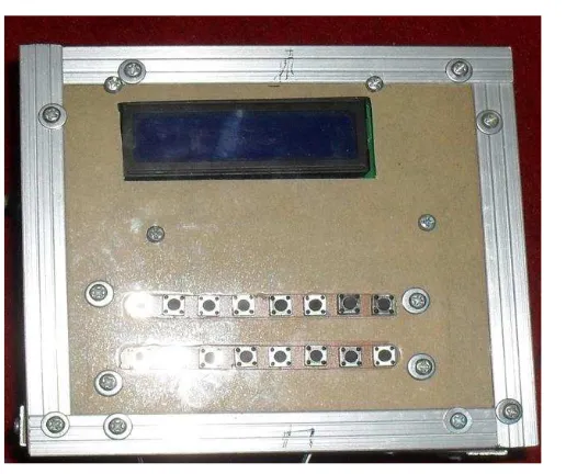
8435 Figure 8: occupancy sensors
Figure 9: outdoor display
CONCLUSION
A tool is needed for a vehicle to control the speed to avoid any unwanted situation such as an accident. Therefore the paper aims to design a tool as a speed indicator. The tool gives a warning if the speed has been exceeding the safe speed. It will be passive or no warning when the speed is less than the setpoint and to be active or give a warning if the speed is greater or equal than the setpoint. The tool is in accordance with the predetermined design specifications that can give a warning when exceeding the safe speed.
REFRENCES:
[1] S. A. Rajab, A. Mayeli, and H. H. Refai, “Vehicle Classification and Accurate Speed Calculation Using Multi- Element Piezoelectric Sensor,” in 2014 IEEE Intelligent Vehicles Symposium Proceedings, 2014, pp. 894–899.
[2] P. Zhang, P. Neti, and S. Grubic, “Sensorless speed estimation of mains-fed induction motors for condition monitoring using motor relays,” in 2015 IEEE Energy Conversion Congress and Exposition (ECCE), 2015, pp. 2840–2845.
[3] J. R. Millan-Almaraz, R. J. Romero-Troncoso, L. M. Contreras-Medina, and A. Garcia-Perez, “Embedded FPGA based induction motor monitoring system with speed drive fed using multiple wavelet
analysis,” in 2008 International Symposium on Industrial Embedded Systems, 2008, pp. 215–220. [4] A. Nadh and N. L. Praba, “Automatic speed and
torque monitoring in induction motors using ZigBee and SMS,” in 2013 IEEE International Conference ON Emerging Trends in Computing, Communication and Nanotechnology (ICECCN), 2013, pp. 733–738. [5] A. Isik, O. Karakaya, P. A. Oner, and M. K. Eker,
“PMDC motor speed control with fuzzy logic algorithm using PIC16F877 micro controller and plotting data on monitor,” in 2009 Fifth International Conference on Soft Computing, Computing with Words and Perceptions in System Analysis, Decision and Control, 2009, pp. 1–4.
[6] N. M. Raharja, Iswanto, M. Faris, and A. I. Cahyadi,
“Hover position quadrotor control with fuzzy logic,” in 2014 The 1st International Conference on Information Technology, Computer, and Electrical Engineering, 2014, pp. 89–92.
[7] N. M. Raharja, Iswanto, O. Wahyunggoro, and A. I. Cahyadi, “Altitude control for quadrotor with mamdani fuzzy model,” in 2015 International Conference on Science in Information Technology (ICSITech), 2015, pp. 309–314.
[8] I. Iswanto, O. Wahyunggoro, and A. I. Cahyadi,
“Quadrotor Path Planning Based On Modified Fuzzy Cell Decomposition Algorithm,” TELKOMNIKA, vol. 14, no. 2, pp. 655–664, 2016.
[9] I. Iswanto, O. Wahyunggoro, and A. Imam Cahyadi,
“Path Planning Based on Fuzzy Decision Trees and Potential Field,” Int. J. Electr. Comput. Eng., vol. 6, no. 1, p. 212, 2016.
[10] T. P. Tunggal, A. Latif, and Iswanto, “Low-cost portable heart rate monitoring based on photoplethysmography and decision tree,” in ADVANCES OF SCIENCE AND TECHNOLOGY FOR SOCIETY: Proceedings of the 1st International Conference on Science and Technology 2015 (ICST-2015), 2016, p. 090004.
[11] Iswanto, Design dan Implementasi Sistem Embedded Mikrokontroler ATMEGA8535 dengan Bahasa Basic. Yogyakarta: Gava Media, 2008.
[12] Iswanto and N. M. Raharja, Mikrokontroller: Teori dan Praktik Atmega 16 dengan Bahasa C. Penerbit Deepublish, 2015.
[13] A. N. N. Chamim and Iswanto, “Implementasi Mikrokontroler Untuk Pengendalian Lampu Dengan
Sms,” in Prosending Retii 6., 2011.