DOI: 10.12928/TELKOMNIKA.v14i2A.4369 92
Welding Robot Kinematics Analysis and Trajectory
Planning
Li Jingwei, Tong Yifei*, Wu Shaofeng, Tan Qingmeng, Li Dongbo
Nanjing University of Science and Technology, School of Mechanical Engineering 401, Nanjing, China *Corresponding author, e-mail: [email protected]
Abstract
Taking PR1400 welding robot as the research object, the structure and link parameters are analyzed and the standard Denavit-Hartenberg method is applied to establish the coordinate system. Then the robot kinematics is analyzed. Matlab Robotics Toolbox is used to build the model and trajectory planning simulation. Thus continuous smooth joints angular displacement, angular velocity, angular acceleration curve and the end motion trajectory curves of PR1400 robot are obtained. Besides, the simulation can allow researchers to avoid kinematics analysis and computational errors, and thereby the robot kinematics analysis and trajectory planning problem are more simple and reliable. The above researches can provide a theoretical basis for PR1400 welding robot trajectory planning in the practical application.
Keywords: Denavit-Hartenberg, Matlab, kinematics analysis, PR1400 welding robot, trajectory planning
1. Introduction
Welding robot technology turns more and more mature with the improvement of industrial automation technology. Therefore, a lot of welding robots have been used in industrial production, the requirements of whose performance are getting increasingly high in order to ensure the welding quality. However, the researches with the robot body have disadvantages of high cost, long cycle and so on. So by simulation technology, kinematics analysis as well as trajectory planning of the robot is a feasible and ideal choice [1]. Many scholars have done researches focusing on the above issues. Wang and Zhou analyzed the structure and parameters of the robot linkages, and utilized the standard Denavit-Hartenberg method to establish the coordinates and the kinematic equation of the linkages. Due to the graphics and matrix calculation ability of Matlab as well as the Robotics Toolbox, the handling robot was modelled and its kinematics, inverse kinematics and trajectory planning were simulated [2]. In Literature, the mathematical simulation model of the offline trajectory planning for six links was built and the simulation results could be demonstrated intuitively and dynamically by using the MATLAB for the solid model of a welding Robot set up by using SolidWorks. Zhao and Sun carried out kinematics and PTP motion control of the 6-DOF robot.
In this paper, PR1400 welding robot is taken as the research object. Firstly, the structure and link parameters are analyzed, and then kinematics of the robot is analyzed by use of D-H coordinate theory [3]. On the basis of kinematics analysis, a three-dimensional model of PR1400 is built by Matlab Robotics Toolbox, basd on which trajectory planning is carried out. Thereby the joints angular displacement, angular velocity, angular acceleration curve of PR1400 robot and the end motion trajectory curves are obtained, and then the operation state of the robot is furthermore analyzed.
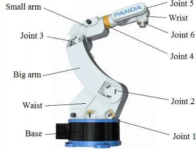
2. Body Structure of PR1400 Welding Robot and its D-H Coordinate System
and twist angle “”, where the joint angle “” is the joint variable, and the other three parameters are constants remain unchanged. Link parameter values are given in Table 1.
Figure 1. PR1400 welding robot body
Figure 2. PR1400 welding robot links coordinate system of D-H
Table 1. PR1400 welding robot links parameters Joint
i
(o) ai(mm) i
(o) di(mm) Range of (o) 1 -90 185 0 420 -170 ~ +170 2 0 760 -90 0 -160 ~ +90 3 -90 150 0 0 -87.5 ~ +77.8 4 90 0 0 456 -180 ~ +180 5 -90 0 0 0 -60 ~ +210 6 0 0 -90 210 -270 ~ +270
3. Forward Kinematics Analysis of PR1400 Welding Robot
Forward kinematics analysis is made to deduce the position and orientation of the end link coordinate system relative to the base coordinate system based on the joints and links variables [6]. According to the PR1400 welding robot link coordinate system established by D-H method and link parameters in Table 1, the homogeneous transformation matrix n 1
n T
represent the position and orientation transformation of the ith link coordinate system relative to the (i-1)th link coordinate system:
i i i i i i i
Thus, kinematics equation of the PR1400 welding robot is got:
x x x x
The end position and orientation expressions of the robot PR1400 can be got by substituting the parameters in Table 1, as follows:
1 2 3 1 2 3 4 1 4 5 1 2 3 1 2 3 5 6 1 2 3 1 2 3 4 1 4 6
4. Establishment of PR1400 Welding Robot Three-Dimensional Model in Matlab
To aim trajectory planning of PR1400 welding robot, the corresponding three-dimensional model is necessary. According to the parameters in Table 1, functions “link” and “robot” in Matlab Robotics Toolbox are used to establish the three-dimensional model of PR1400 robot [7]. The programs of the built robot model are as follows:
drivebot(r);
xlabel('x/m');ylabel('y/m');zlabel('z/m');
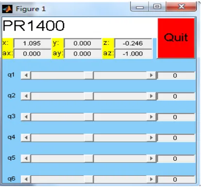
The above programs are run in Matlab, and the initial state of the PR1400 robot three-dimensional model (each joint angle is zero) is built, as shown in Figure 3, and PR1400 robot slider controls chart is shown in Figure 4.
Figure 3. PR1400 robot three-dimensional model
Figure 4. PR1400 robot slider controls chart
Each joint rotation of the PR1400 can be realized by driving sliders in Figure 4. As can be seen, the first three joints rotation changes the position of the wrist, and the last three joints rotation adjustments wrist orientation to be accordance with the actual operation of the robot.
5. Verify the PR1400 Robot Three-Dimensional Model
model end center position and orientation information by function “fkine” in Robotics Toolbox. Finally, compare the two results and verify the established model. Here are three groups of joint variable values that randomly selected:
q1=[1.0472 0.5236 -0.7854 0 0.7854 -1.5708] q2=[0.5236 0.7854 1.0472 1.5708 0 0.7854] q3=[0.7854 1.0472 0 1.0472 1.5708 3.1416] Appropriate programs are as follows: T1=fkine(r,q1)
T2=fkine(r,q2) T3=fkine(r,q3)
Each of T1, T2 and T3 represents one end position and orientation matrix “0 6 T ”as shown in formula (2). Then end position coordinates can be sourced. The comparison of the end position simulation and computation values of PR1400 robot is shown in Table 2:
Table 2. The comparison of simulation and computation value
Group Simulation value Computation value Px Py Pz Px Py Pz 1 0.5005 0.8670 -0.5435 0.5005 0.8670 -0.5435 2 0.0349 0.0201 -0.0899 0.0349 0.0201 -0.0899 3 0.0076 0.2648 -0.5052 0.0076 0.2648 -0.5052
As can be seen from Table 2, simulation and computation value are exactly equal, which shows the PR1400 model built is correct and of high accuracy. So the model can be used to trajectory planning.
6. PR1400 Welding Robot Trajectory Planning and Simulation
Trajectory planning is based on the task that robots need to complete, and construct a time history of each joint movement, get the function of time of the end-effector position and orientation, guarantee to achieve the desired space movement of the robot [8, 9]. Trajectory planning can be carried out also in the operating space or the joint space. The trajectory planning in this study, point to point planning is took in joint space, that is, the angle of each joint is expressed as a function of time to describe the robot movement trajectory during the period [10, 11].
6.1. PR1400 Welding Robot Trajectory Planning
Robotics Toolbox is used to trajectory planning of PR1400 robot in joint space, and trajectory planning function “jtraj” is called. Function “jtraj” uses a 7-degree polynomial, that is the joint angular displacement is a polynomial of degree 7 of time, and the default of the initial and final velocity and acceleration are all zero. Function “jtraj” satisfies the following equation and known conditions: which can be used to obtain a set of solutions of coefficients that meet the conditions. Here function “jtraj” is used for the PR1400 robot trajectory planning, programs are as follows:
qz=[0 0 0 0 0 0];
qr=[-0.4607 -1.5708 0.06283 -0.3769 1.5498 -0.5654]; t=[0:0.1:2];
The programs are run to observe the whole process of PR1400 model motion from the initial position “qz” to the end position “qr”, where “qz” represents the joint angular displacement of the initial position, “qr” represents the joint angular displacement of the end position, “t” is the robot running time, “q” is a matrix, each row represents the joint angular displacement of a time sampling dot, “qd” indicates the corresponding angular joint velocity, and “qdd” indicates the corresponding angular joint acceleration. The PR1400 robot three-dimensional end position “qr” is shown in Figure 5 as well as angular displacement and angular velocity, angular acceleration curve of the PR1400 robot movement shown in Figure 6 and Figure 7.
Figure 5. PR1400 robot three-dimensional model
Figure 7. Joint 4-6 displacement, velocity and acceleration curves
6.2. The End Trajectory Simulation of PR1400 Robot
The end position and orientation matrix can be obtained by function “jtraj”, and thus the end position coordinates are gotten. Furthermore, the robot end-effector trajectory is simulated. Here still use the initial position “qz” and end position “qr”, and the same running time t=2s as shown in section 6.1. Add the following programs after programs the section 1:
u=T(1,4,:);v=T(2,4,:);w=T(3,4,:);
x=squeeze(u);y=squeeze(v);z=squeeze(w); subplot(1,3,1);plot(t,x);xlabel('t/s');ylabel('x/m'); subplot(1,3,2);plot(t,y);xlabel('t/s');ylabel('y/m'); subplot(1,3,3);plot(t,z);xlabel('t/s');ylabel('z/m');
figure(2);plot3(x,y,z,'Linewidth',3);xlabel('x/m');ylabel('y/m');zlabel('z/m'); box on;grid on;
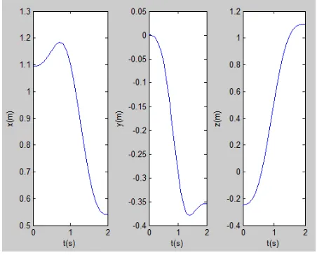
Run the above programs to obtain the PR1400 robot end trajectory curve of x, y, and z-axis directions, as shown in Figure 8, as well as the end space trajectory curve, as shown in Figure 9.
Figure 9. PR1400 robot end space trajectory curve
7. Conclusions
As can be seen, each joint angular displacement gradually changes from 0 rad to the end joint angle set in “qr” in the first column of Figure 6 and 7. Each joint angular velocity of the second column shows both initial and end velocity are 0, and the maximum velocity is in the middle at the time t=1s. The angular acceleration curve is from the third column, as can be seen, both initial and end acceleration are 0 of each angular, and two extreme values appear in the movement with a positive and a negative. In summary, the angular displacement curves are smoothing and the velocity and acceleration curves are continuously and without mutation, which show that the robot is running relatively stable in the work process. So the entire structure will produce little vibration. As can be seen from the end running trajectory in Figure 8 and 9, PR1400 robot moves from the initial position “qz” to the end position “qr” after 2s and the time sampling interval is 0.1s. Its movement curve is continuous and smooth, and thus illustrates the shock of the robot is very small during operation, and thereby can assure the quality of welding.
Acknowledgements
This work was financially supported this work was financially supported by Prospective joint research project of Jiangsu Province (NO. BY2015004-05), the Jiangsu Provincial Six Talent Peaks Project (NO. 2015-ZBZZ-006), and Science and Technology Achievements Transformation of Jiangsu Province (2015-67, High local industrial robots and intelligent equipment development and industrialization, Nanjing PANDA Electronics Equipment Co., Ltd). The supports are gratefully acknowledged. The authors would also acknowledge the Editor.
References
[1] Wang Zhixing, Fan Wenxin, Zhang Baocheng, SHI Yuanyuan. Kinematical analysis and simulation of industrial robot based on Matlab. Journal of Mechanical & Electrical Engineering. 2012; 29(1): 33-37. [2] T Sutikno. FPGA for Robotic Applications: from Android/Humanoid Robots to Artificial Men.
TELKOMNIKA (Telecommunication Computing Electronics and Control). 2011; 9(3): 401-402. [3] Soni RA. A Study on Android Application Development. Journal of Telematics and Informatics. 2013;
1(2): 89-96.
[4] B He, L Han, Y Wang, S Huang, L Liu. Kinematics analysis and numerical simulation of a manipulator based on virtual prototyping. International Journal of Advanced Manufacturing Technology. 2014; 71(5-8): 943-963.
[5] MK Sutar, PM Pathak, AK Sharma, NK Mehta, VK Gupta. Forward kinematic analysis of in-vivo robot for stomach biopsy. Journal of Robotic Surgery. 2012; 7(3): 281-287.
[7] Yuehai Wang, Ning Chi. Path Planning Optimization for Teaching and Playback Welding Robot. TELKOMNIKA Indonesian Journal of Electrical Engineering. 2013; 11(2): 960-968.
[8] P Corke. A Robotics Toolbox for MATLAB. IEEE Robotics & Automation Magazine. 1996; 3(1): 24-32.
[9] T Zhang, S Chen. Path Planning and Computer Simulation of a Mobile Welding Robot. Springer Berlin Heidelberg. 2010; 88: 421-428.
[10] Z Li, Z Huang, Y Huang. Design of Spot Welding Robot. TELKOMNIKA Indonesian Journal of Electrical Engineering. 2013; 11(11): 6267-6273.