UNIVERSITI TEKNIKAL MALAYSIA MELAKA
FINITE ELEMENT ANALYSIS
OF
CAR ALLOY WHEEL
Thesis submitted in accordance with the partial requirements of the
Universiti Teknikal Malaysia Melaka for the
Bachelor of Manufacturing Engineering (Manufacturing Design)
By
MOHO ZUL HAZMI BIN MHO FAUZY
Faculty ofManufacturing Engineering
UTeM Library (Pind.l/2007)
UNIVERSITI TEKNIKAL MALAYSIA MELAKA
BORANG PENGESAHAN STATUS TESIS*
JUDUL: FINITE ELEMENT ANALYSIS OF CAR ALLOY WHEEL
SESI PENGAJIAN : 2007/2008
Saya MOHD ZUL HAZMI BIN MHD FAUZY
(HURUF BESAR)
mengaku membenarkan tesis (PSM/Sarjana/Doktor Falsafah) ini disimpan di Perpustakaan Universiti Teknikal Malaysia Melaka (UTeM) dengan syarat-syarat kegunaan seperti berikut:
1. Tesis adalah hak milik Universiti Teknikal Malaysia Melaka .
2. Perpustakaan Universiti Teknikal Malaysia Melaka dibenarkan membuat salinan untuk tujuan pengajian sahaja.
3. Perpustakaan dibenarkan membuat salinan tesis ini sebagai bahan pertukaran antara institusi pengajian tinggi.
4. **Sila tandakan (--./)
D
SULITD
TERHAD(Mengandungi maklumat yang berdarjah keselamatan atau kepentingan Malaysia yang termaktub di dalam AKTA RAHSIA RASMI 1972)
(Mengandungi maklumat TERHAD yang telah ditentukan oleh organisasi/badan di mana penyelidikan dijalankan)
G
TIDAK TERHAD(TAN4 : ;PENULIS)
Alamat Tetap:
654
JALAN AMAN 13, TAMAN AMAN, ANAK BUKIT06550
ALOR STAR KEDAH.Tarikh: I
Si
o
>
og
I
Cop Rasmi:
WAHYON. SAPTO WIDODO
ヲGセョウケ。イセB@
Fakutti Kejuruteraan r embuatan Universiti Te• .:ikal H;olaysia Melaka
Karung Be,. :•ci 1200. Ayer Keroh
Tarikh: _ _ _ 7_M_5o_ M_e_lak_a _ _ _ _
* Tesis dimaksudkan sebagai tesis bagi ljazah Doktor Falsafah dan Sarjana secara penyelidikan , atau disertasi bagi pengajian secara kerja kursus dan penyelidikan, atau Laporan Projek Sarjana Muda (PSM) .
** Jika tesis ini SULIT atau TERHAD, sila lampirkan surat daripada pihak berkuasa/organisasi berkenaan
DECLARATION
I hereby, declare this thesis entitled "Finite Element Analysis of Car Alloy Wheel" is the
result of my own research except as cited in the references.
Signature
Author's Name
Date
Tセ@
ᄋᄋᄋᄋᄋᄋᄋᄋᄋᄋᄋᄋᄋᄋᄋᄋᄋᄋᄋᄋᄋᄋᄋᄋᄋᄋ
セ
ᄋᄋᄋᄋᄋᄋᄋᄋᄋᄋᄋᄋᄋᄋᄋᄋᄋᄋᄋᄋᄋᄋᄋᄋᄋᄋᄋᄋᄋᄋᄋᄋᄋ
ᄋᄋ ᄋᄋᄋᄋᄋᄋᄋᄋᄋᄋᄋᄋᄋ@
Mohd Zul Hazmi Bin Mhd Fauzy
25th March 2008
APPROVAL
This thesis submitted to the senate ofUTeM and has been accepted as partial
fulfillment of the requirements for the degree of Bachelor of Manufacturing Engineering
(Manufacturing Design). The members of the supervisory committee are as follow:
Main Supervisor
(Mr Wahyono Sapto Widodo)
ABSTRACT
Finite element analysis is one of the methods to analyze the product by doing a
simulation. This method is quite long used in manufacturing industry and had earned
many benefits to the company who used this kind of software. It is because this
simulation can reduce the times, costs and can improving the quality of the product.
The tests on the product can be done by using the simulation without producing
the real product to do the tests. The engineers just make the design and its specification
of the product before ready to do the simulation. By this method, not only the time can
be reduced but the cost for producing the testing product also can be reduced. The costs
earning from the reducing can be invest to develop the upcoming products.
ABSTRAK
'Finite Element Analysis' merupakan salah satu cara untuk menganalisis sesuatu
produk dengan menggunakan kaedah simulasi. Kaedah ini sudah agak lama digunakan
di dalam industri pembuatan dan telah mendatangkan banyak keuntungan kepada
syarikat yang mengendalikannya. Ini kerana kaedah simulasi ini dapat menjimatkan dari
segi masa, kos, dan juga dapat meningkatkan kualiti sesuatu produk.
Ujian terhadap sesuatu produk dapat dijalankan dengan hanya menjalankan
simulasi tanpa perlu untuk menghasilkan produk diuji . Jurutera hanya perlu
menghasilkan rekabentuk dan juga spesifikasi untuk produk sebelum sedia untuk diuji.
Dengan kaedah ini, bukan masa sahaja dapat dijimatkan malah kos untuk menghasilkan
bahan ujikaji juga tidak diperlukan lagi. Kos yang telah dapat dijimatkan boleh
digunakan untuk membangunkan produk yang baru.
DEDICATION
To my beloved father, mother and to all of my friends especially who had helped me for
finish up this project.
ACKNOWLEDGEMENT
First of all, I want to thank to Allah SWT for giving me strength and wealthy to
complete my Projek Sarjana Muda (PSM) titled "Finite Element Analysis of Car Alloy
Wheel". Then, I also would like to thank my supervisor, Mr. Wahyono Sapto Widodo
who had gives me more knowledge and guide to complete this project, all of my friends
especially Mr. Rizal from class BMCD who had monitoring me in my analysis by using
Nastran/Patran software and also who either directly or indirectly helped me in this task.
Thanks you very much.
TABLE OF CONTENTS
DECLARATION ... ... ... ... ... ... ... ... ... ... ... .... .. !
APPROVAL ... ... . ... .. ... ... . ... ... ... ... .. .. ... ... .II
ABSTRACT ... ... ... ... ... ... .III
ABSTRAK .. .... ... ... ... ... ... ... . .. ... . .. ... ... ... . . ... VI
DEDICATION ... ... ... ... ... ... .. ... ... .... .. ... V
ACKNOWLEDGEMENT .... .. ... ... ... ... ... ... ... ... . ... ... .. VI
TABLE OF CONTENTS ... ... . ... ... . .. .. VIII
LIST OF FIGURES . ... .... ... .... ... ... ... .... . .... .. ... ... . .. XII .
LIST OF TABLES .. .. . ... .... ... .. . . ... .. ... . ... ... . XIII
CHAPTER 1 - INTRODUCTION
1.1 Background . .. ... . . .. .... ... .. .... ... .... . ... .. 1
1.2 Problem Statement .. . ... ... . ... . .... ... 2
1.3 Objective . .. .... ... . . ... ... . ... 3
1.4 Scope ... .. ... ... ... ... 3
CHAPTER 2-LITERATURE REVIEW 2.1 Introduction to FEA ... .. ... .4
2.1 .1 Pre-processing ... ... ... ... ... ... .. ... . ... 5
2.1.2 Analysis . ... .. ... . ... .. .. .. 6
2.1.3 Post-processing ... ... ... . ... ... ... ... .... 6
2.2 Finite E lement Analysis Principles . .. ... ... .. ... ... 7
2.3 Types of Engineering Analysis . ... ... ... . ... ... ... . ... 1 0 2.4 Applications ofFEA ... .. .... ... .... ... ... ... .. . .. ... . ... . .... 11
2.4.1 Applications of FEA to the mechanical engineering industry .... .. 11
2.4.2 Computer-aided design and finite element analysis in industry .... 12
2.5 Introduction to Alloy Wheels .. ... .. ... ... . ... .. .. ... ... ... ... ... 14
2.5.1 Illustration of Alloy Wheels . ... .... . .... . .. .... .. .. ... ... .... 14
2.5.2 Manufacturing of Alloy wheels .... .. .... . .. . ... . . ... .16
2.6 Inspection of Alloy Wheels . .. ... 17
2.7 TUV Testing ... ... . .. . ... . .... ... . .. .. . ... .. 17
2.7.1 Fatigue Testing ... .. ... . ... . ... 18
2.7 .2 Rolling Test.. ... . ... .. . . . ... ... . .. . . . ... . ... 18
2.7.3 Impact Test. ... . ... ... ... ... ... ... ... ... ... . ... 18
2.7.4 Test Drive .... . ... ... . ... .. ... ... .. ... . ... 18
2.8 CATIA Software ... . ... . ... . . ... .... ... .. .... 19
2.8.1 Features and Capabilities . . .. . ... . ... ... .. ... .. . .... .. 20
2.8.2 CATIA in Industries ... .. ... . ... 21
2.9 Nastran!Patran Software ... . . ... ... . 22
2.10 Safety Factor ... . ... ... ... . ... .... 25
CHAPTER 3- METHODOLOGY 3.1 Research Design ... . ... .... .... .... ... .... ... . . ... .. . ... . ... 27
3.2 Study the Literature Review ... ... ... .. .. .. .. ... .. .. .. .. ... ... 28
3.3 Design by using CA TIA .. ... ... .. .. ... .. ... ... . ... ... .... ... ... . ... 29
3.4 Material Selection ... . ... .... .. ... .. .29
3.5 Testing/simulation ... . ... . ... . ... . .. ... ... .... 30
3.6 Result/analysis ... ... .. ... . ... ... .. .. .. .. .... ... ... . ... .... . . ... . ... 30
3.7 Discussion ... ... ... ... ... ... ... ... .... . ... 3 1 3.8 Conclusion ... .... ... ... ... ... ... ... ... 31
CHAPTER 4 -RESULT/ ANALYSIS 4.1 Type of Analysis ... . ... .. ... ... ... ... ... ... . ... ... ... ... .... . ... 32
4.2 Design Consideration ... . ... ... ... ... .. .. . . .. ... ... ... . .... 33
4.3 Material Selection .... . .. ... ... . .. . ... ... . ... .. . . .. .. .. 34
4.4 Nastran/Patran Analysis ... . . ... ... 35
4.5 Result. ... . ... ... ... ... ... .... .. . ... ... ... . ... 36
4.5.1 Case 1 (Static) . .. . . .... ... ... ... . . . .... .. ... . . . ... .... ... .. 36
4.5.2 Case 2 (Movement) ... . ... .. ... . ... . ... 38
4.5.3 Case 3 (Cornering) ... . ... . ... . . ... ... . . .41
4.6 Safety Factor ... ... . ... . .. . .... 45
CHAPTER 5-DISCUSSION ... .. ... ... .. ... . ... . ... .. . ... . ... .46
CHAPTER 6-CONCLUSION .. . . .... .. ... . .... ... .. ... . ... ... ... ... .48
REFERENCES ... ... ... .... ... . .... . .... .... ... 49
APPENDIX A . ... .. .... . ... . ... .. .. .. ... .... ... ... ... ... . .. .. . . ... ... .. 51
APPENDIX B ... ... ... ... ... ... ... .... . ... ... 53
APPENDIX C ... . ... .... .... .... ... 55
LIST OF FIGURES
Figure! - FEA analysis ... . . ... . . ... .. ... ... . ... .... .. ... ... ... ... 5Figure 2 - FEA using nodes ... . ... ... . ... ... . .. . . ... . .. . ... 7
Figure 3 - FEA using pressure ... ... ... ... . ... .. ... 8
Figure 4-Amount of deformation ... ... ... ... .... ... . ... ... .... .. ... .... ... 10
Figure 5 -Illustration of alloy wheel. .. . ... .. ... .. ... .. 14
Figure 6- Forging process for alloy wheel.. ... . ... .. .. ... ... . ... .... .16
Figure 7- CATIA software ... ... ... ... . ... ... ... ... ... ... 19
Figure 8-Nastran/Patran software ... . .... ... ... ... .. . ... . . . ... . .... . ... .. 23
Figure 9-Design of the alloy whee l. ... .. . . .. .... 32
Figure 10-Force applied in case 1 .. ... ... ... ... ... ... ... .. ... .... 35
Figure 11 - Analysis result for case 1 ... ... ... .... .. . ... ... . ... ... .... ... ... 36
Figure 12- Force applied in case 2 ... . ... ... ... ... ... .. . 37
Figure 13- Resultant of the vector for case 2 .... . ... . ... 38
Figure 14- Analysis result for case 2 ... . ... . .. ... ... . ... 39
F igure 15 - Force applied in case 3 .... . ... ... .... .. . . ... . ... . ... .40
Figure 16- Resultant ofthe vector for case 3 (X-axis vs Y-axis) .... ... ... .. ... .41
Figure 17- Resultant of the vector for case 3 (Y-axis vs Z-axis) ... . ... .. .42
Figure 18 -Analysis result for case 3 ... .. ... .. ... ... ... .43
LIST OF TABLES
TABLE
SUBJECT
PAGE
Table 1 - Safety factor value found in simulation ... ... ... ... ... ... .... ... II
CHAPTER!
INTRODUCTION
1.1 Background
Finite Element Analysis (FEA) was first developed in 1943 by R. Courant, who
utilized the Ritz method of numerical analysis and minimization of variational calculus to
obtain approximate solutions to vibration systems. Shortly thereafter, a paper published
in 1956 by M. J. Turner, R. W. Clough, H. C. Martin, and L. J. Topp established a
broader definition of numerical analysis. The paper centered on the "stiffness and
deflection of complex structures".
By the early 70's, FEA was limited to expensive mainframe computers generally
owned by the aeronautics, automotive, defense, and nuclear industries. Since the rapid
decline in the cost of computers and the phenomenal increase in computing power, FEA
has been developed to an incredible precision. Present day supercomputers are now able
to produce accurate results for all kinds of parameters.
FEA consists of a computer model of a material or design that is stressed and
analyzed for specific results. It is used in new product design, and existing product
refinement. A company is able to verify a proposed design will be able to perform to the
client's specifications prior to manufacturing or construction. Modifying an existing
product or structure is utilized to qualify the product or structure for a new service
condition. In case of structural failure, FEA may be used to help determine the design
modifications to meet the new condition.
There are generally two types of analysis that are used in industry: 2-D modeling,
and 3-D modeling. While 2-D modeling conserves simplicity and allows the analysis to
be run on a relatively normal computer, it tends to yield less accurate results. 3-D
modeling, however, produces more accurate results while sacrificing the ability to run on
all but the fastest computers effectively. Within each of these modeling schemes, the
programmer can insert numerous algorithms (functions) which may make the system
behave linearly or non-linearly. Linear systems are far less complex and generally do not
take into account plastic deformation. Non-linear systems do account for plastic
deformation, and many also are capable of testing a material all the way to fracture.
1.2 Problem statement
For this study, the main problems that will consider are to study and redesign the
previous design. The story of a wheel begins with a design idea. Design specification
documentation is drawn up outlining the basic definition, appearance and the technical
structure of the wheel (one-section, two-section or multi-section). This idea is then
brought to life using special CAD software to create the first 3D model for testing. The
software allows the wheel to be turned three-dimensionally and for improvements to be
made easily. Many specifications that must be consider before the alloy wheels are
designed and ready to produce. It' s about the ability of the alloy wheels to support the
car whether in static or dynamic situation. The correct in selected material is also
important to make sure the alloy wheels are good in quality and its performances.
The process to develop a new design of alloy wheels will cause a high costs. With
the new technology, we try avoiding the test by using the actual product which is can
help to reduce the previous costs. By using the new software today, we not only can
design the alloy wheels but also can analysis the product in details. The defects from the
design can be detected when doing a simulation on the product. By using FEA
simulation, the more precise and accurate result will be get.
1.3 Objective
The main objectives that have to be in consideration for this project; stated as below:
a) To study about the alloy wheel design nowadays.
b) Try to design the alloy wheel by using CA TIA software.
c) Do the test via simulation by using the CA TIA or Nastran software.
d) Learn how to improve the design of the alloy wheels.
e) Analyzed the results and make future work recommendations.
1.4 Scope
The task will be started by studying about the alloy wheels before try to analysis
the product. The alloy wheel then must be design by using CA TIA software. The design
is very important in getting a good result during the analysis. The analysis can be done by
simulate the design using CA TIA/Patran.
There are too many tests that must be considered before an alloy wheels are ready
to enter the market. For this project, static test were choose to analyze on the design of
the alloy wheels. The result will be analyzed and the recommendation to improve the
design of the alloy wheels was list out based on the result obtained.
2.1 Introduction to FEA
CHAPTER2
LITERATURE REVIEW
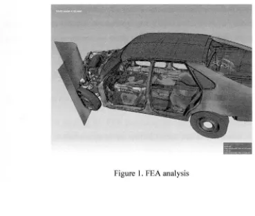
Computer-aided engineering (CAE) is the application of computer software in
engineering to evaluate components and assemblies. It encompasses simulation,
validation, and optimization of products and manufacturing tools. The primary
application of CAE, used in civil, mechanical, aerospace, and electronic engineering,
takes the form of FEA alongside computer-aided design (CAD).
In general, there are three phases in any computer-aided engineering task:
a) Pre-processing - defining the finite element model and environmental factors to
be applied to it
b) Analysis solver- solution of finite element model
c) Post-processing of results using visualization tools
Figure 1. FEA analysis
2.1.1 Pre-processing
The first step in using FEA, pre-processing, is constructing a finite element model
of the structure to be analyzed. The input of a topological description of the structure's
geometric features is required in most FEA packages. This can be in either ID, 2D, or 3D
form , modeled by line, shape, or surface representation, respectively, although nowadays
3D models are predominantly used. The primary objective of the model is to realistically
replicate the important parameters and features of the real model. The simplest
mechanism to achieve modeling similarity in structural analysis is to utilize pre-existing
digital blueprints, design files, CAD models, and/or data by importing that into an FEA
environment. Once the finite element geometric model has been created, a meshing
procedure is used to define and break up the model into small elements. In general , a
finite element model is defined by a mesh network, which is made up of the geometric
arrangement of elements and nodes. Nodes represent points at which features such as
displacements are calculated. FEA packages use node numbers to serve as an
[image:17.528.54.423.123.436.2]identification tool in viewing solutions in structures such as deflections. Elements are
bounded by sets of nodes, and define localized mass and stiffuess properties of the model.
Elements are also defined by mesh numbers, which allow references to be made to
corresponding deflections or stresses at specific model locations.
2.1.2 Analysis (computation of solution)
The next stage of the FEA process is analysis. The FEM conducts a series of
computational procedures involving applied forces , and the properties of the elements
which produce a model solution. Such a structural analysis allows the determination of
effects such as deformations, strains, and stresses which are caused by applied structural
loads such as force, pressure and gravity.
2.1.3 Post-processing (visualization)
These results can then be studied usmg visualization tools within the FEA
environment to view and to fully identify implications of the analysis. Numerical and
graphical tools allow the precise location of data such as stresses and deflections to be
identified.
A wide range of objective functions (variables within the system) are available for
minimization or maximization:
a) Mass, volume, temperature
b) Strain energy, stress strain
c) Force, displacement, velocity, acceleration
d) Synthetic (User defined)
There are multiple loading conditions which may be applied to a system. Next to Figure
3, some examples are shown:
a) Point, pressure (Figure 3), thermal, gravity, and centrifugal static loads
b) Thermal loads from solution of heat transfer analysis
c) Enforced displacements
d) Heat flux and convection
e) Point, pressure and gravity dynamic loads
Figure 3. FEA using pressure
[image:19.529.170.370.446.642.2]·
2.2 Finite Element Analysis Principles
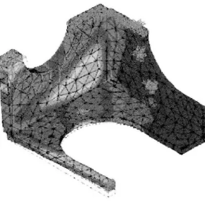
FEA uses a complex system of points called nodes which make a grid called a
mesh (Figure 2). This mesh is programmed to contain the material and structural
properties which define how the structure will react to certain loading conditions. Nodes
are assigned at a certain density throughout the material depending on the anticipated
stress levels of a particular area. Regions which will receive large amounts of stress
usually have a higher node density than those which experience little or no stress. Points
of interest may consist of: fracture point of previously tested material, fillets, corners,
complex detail, and high stress areas. The mesh acts like a spider web in that from each
node, there extends a mesh element to each of the adjacent nodes. This web of vectors is
what carries the material properties to the object, creating many elements.
Figure 2. FEA using nodes
[image:20.528.162.367.390.524.2]Each FEA program may come with an element library, or one is constructed over time.
Some sample elements are:
a) Rod elements
b) Beam elements
c) Plate/Shell/Composite elements
d) Shear panel
e) Solid elements
f) Spring elements
g) Mass elements
h) Rigid elements
i) Viscous damping elements
Many FEA programs also are equipped with the capability to use multiple materials
within the structure such as:
a) Isotropic, identical throughout
b) Orthotropic, identical at 90 degrees
c) General anisotropic, different throughout
2.3 Types of Engineering Analysis
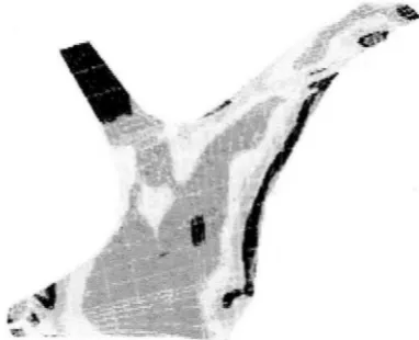
Structural analysis consists of linear and non-linear models. Linear models use simple
parameters and assume that the material is not plastically deformed. Non-linear models
consist of stressing the material past its elastic capabilities. The stresses in the material
then vary with the amount of deformation as in Figure 4.
Vibrational analysis is used to test a material against random vibrations, shock, and
impact. Each of these incidences may act on the natural vibrational frequency of the
material which, in tum, may cause resonance and subsequent failure.
Figure 4. amount of deformation
Fatigue analysis helps designers to predict the I ife of a material or structure by showing
the effects of cyclic loading on the specimen. Such analysis can show the areas where
crack propagation is most likely to occur. Failure due to fatigue may also show the
damage tolerance of the material.
[image:22.528.181.372.338.493.2]Heat Transfer analysis models the conductivity or thermal fluid dynamics of the material
or structure. This may consist of a steady-state or transient transfer. Steady-state transfer
refers to constant thermo properties in the material that yield linear heat diffusion.
Results of Finite Element Analysis
FEA has become a solution to the task of predicting failure due to unknown
stresses by showing problem areas in a material and allowing designers to see all of the
theoretical stresses within. This method of product design and testing is far superior to
the manufacturing costs which would accrue if each sample was actually built and tested.
2.4 Applications of FEA
2.4.1 Applications of FEA to the Mechanical Engineering Industry
A variety of specializations under the umbrella of the mechanical engineering
discipline such as aeronautical, biomechanical, and automotive industries all commonly
use integrated FEA in design and development of their products. Several modem FEA
packages include specific components such as thermal, electromagnetic, fluid, and
structural working environments. In a structural simulation FEA helps tremendously in
producing stiffness and strength visualizations and also in minimizing weight, materials,
and costs. FEA allows detailed visualization of where structures bend or twist, and
indicates the distribution of stresses and displacements. FEA software provides a wide
range of simulation options for controlling the complexity of both the modeling and the
analysis of a system. Similarly, the desired level of accuracy required and the associated
computational time requirements can be managed simultaneously to address most
engineering applications. FEA allows entire designs to be constructed, refined, and
optimized before the design is manufactured. This powerful design tool has significantly
improved both the standard of engineering designs and the methodology of the design
process in many industrial applications. The introduction of FEA has substantially
decreased the time taken to take products from concept to the production line. It is primarily through improved initial prototype designs using FEA that testing and
development have been accelerated. In summary, the benefits of FEA include increased
accuracy, enhanced design and better insight into critical design parameters, virtual
prototyping, fewer hardware prototypes, a faster and less expensive design cycle,
increased productivity, and increased revenue.
2.4.2 Computer-aided Design and Finite Element Analysis
inIndustry
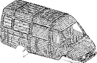
The ability to model a structural system in 3D can provide a powerful and
accurate analysis of almost any structure. 3D models, in general, can be produced using a
range of common computer-aided design packages. Models have the tendency to range
largely in both complexity and in file format, depending on 3D model creation software
and the complexity of the model's geometry. FEA is a growing industry in product
design, analysis, and development in engineering. The trend of utilizing FEA as an
engineering tool is growing rapidly. The advancement in computer processing power,
FEA, and modeling software has allowed the continued integration of FEA in the
engineering fields of product design and development. In the past, there have been many
issues restricting the performance and ultimately the acceptance and utilization of FEA in
conjunction with CAD in the product design and development stages. The gaps in
compatibility between CAD file formats and FEA software limited the extent to which
companies could easily design and test their products using the CAD and FEA
combination, respectively. Typically, engineers would use specialist CAD and modeling
software in the design of the product and then wish to export that design into a FEA
package to test. However, those engineers who depended on data exchange through
custom translators or exchange standards such as IGES or STEP cite occasional
reliability problems causing unsuccessful exchange of geometry. Thus, the creation of
many models external to FEA environments was considered to be problematic in the
success of FEA.