AIR CONDITIONING SYSTEM POWERED BY SMALL ENGINE
ABDUL HAFIZ BIN ABD HAMID
This report was adduced in partial fulfillment for award condition of Bachelor of Mechanical Engineering (Thermal Fluid)
Faculty of Mechanical Engineering Universiti Teknikal Malaysia Melaka
“I admit that had read this dissertation and in my opinion this dissertation is satisfactory in the aspect of scope and quality for the bestowal of Bachelor of
Mechanical Engineering (Thermal Fluid)”
Signature:
Name of Supervisor 1: Mr. Safarudin Gazali Herawan Date:
Signature:
i
“I hereby, declare this report is the result of my own works and research except the as cited in the references”
Signature :………..
iii
ACKNOWLEDGEMENT
Firstly thanks to ALLAH for given me a chance to experience this entire thing in my life and good health condition. Special thanks to Mr. Safarudin Gazali Herawan for her concern time to a guide me to accomplish the PSM I&II with strong mechanical and technical experience. I confidence with the basic experience on this research will help me to explore more things on real engineering field. For my family and especially for my mom, thanks for supporting me and you are my spirit. Not forget for my
ABSTRAK
Kajian ini adalah untuk mengukur kecekapan satu konsep baru pendingin udara yang direka khas untuk aplikasi pengunaan komersial bagi jangka waktu sementara dan berekreasi dimana enjin kecil digunakan bagi mengganti penggunaan elektrik.
Penulisan kajian ini adalah bermula daripada kajian ilmiah yang dilakukan bagi
memahami konsep system penyaman udara dan keperluanya. Daripada maklumat yang sedia ada, pemilihan dilakukan bagi memilih komponen yang bersesuaian bagi
v
ABSTRACT
An investigation is to measure the performance of new concept system of air conditioning system undertaken into cooling needs for commercial and recreational temporary air conditioning (A/C) where powered by small engine replace electrical power supply source. A research was starting from literature review to understand the basic principle of air conditioning system and the requirement. From the information, the suitable component was select to accomplish the system function such as refrigerant type and small engine unit. As the result, R134a was most suitable and environmentally safe to use on this system. It has lowest global warming potential and for the same reason, four-stroke engine was use and it more reasonable from two stroke engine. Finally, the system was design by using the selected component from previous to form a complete system with basic component such as refrigerant’s compressor, evaporator, condenser, expansion valve and small petrol engine unit. The performance of this system was undertaken by experimentally. First experiment method is design to calculate the cooling load of one lecture room and aspect to be cool by using this system. Last experiment is the most important on these research, its was use to
CONTENT
2.0 Air conditioning system 5
2.1 Automotive air conditioning system 8
2.1.1 Compressor 9
2.1.2 Condenser 9
2.1.3 Evaporator 10
2.1.4 Pressure regulating devices 11
2.1.5 Receiver drier 12
2.1.6 Accumulator 12
2.2 Thermodynamic principle of
refrigeration and heat pump 13
2.2.1 Reverse Carnot cycle 15 2.2.2 The Ideal vapour compression
vii
2.4.1 Two stroke cycle engine
(petrol engine) 29
2.4.2 Four-stroke cycle (petrol engine) 31
2.5 The cooling load 33
2.5.1 Cooling load calculation
procedures 33
CHAPTER III METHODOLOGY
3.0 Introduction 36
3.1 Design 37
3.3 Determine by experiment 39
3.3.1 Cooling capacities 39
3.3.2 3.3.3 Efficiency of system 41 3.4 Determine by previous study 42
3.4.1 Selecting refrigerant 42
3.4.2 Selecting engine 44
3.4.3 Selecting air conditioning system 45 CHAPTER IV RESULT
4.0 Introduction 46
4.1 Fabrication result 46
4.1.1 Fabrication of chassis 47 4.1.2 Joining process 49 4.1.3 Preparation of air conditioning parts 52 4.1.4 Assemble process 54
4.2 Performance test result 56
CHAPTER V DISCUSSION & ANALYSIS
5.1 Slope of cooling effect. 64 5.2 Coefficient of performance 67 5.3 Power requirement and cooling capacity. 69 CAHPTER VI CONCLUSION & RECOMMENDATION 76
REFERENCES 77
BIBLIOGRAPHY 79
GLOSSARY 81
ix
LIST OF TABLE
NUMBER TILTLE PAGE
2.1 The boiling point for R-12,R-22, and R-134a
vary depending on pressure. 27
4.1 Raw data from performance test. 57
4.1 Raw data from performance test (cont). 58
5.1 Condenser and evaporator average temperature for every
minute. 66
5.1 Condenser and evaporator average temperature for every
minute. (cont) 67
LIST OF FIGURE
NUMBER TILTLE PAGE
2.1 Minimal air conditioning 6
2.2 Basic component of car air conditioning system 8 2.3 The objective of a refrigerator is to remove heat (Q ) L
from the cold medium; the objective of a heat pump
is to supply heat (QH) to a warm medium 13 2.4 Schematic of a Carnot refrigerator and T-s diagram
of the reversed Carnot cycle 16
2.5: Schematic and T-s diagram for the ideal vapor-
compression refrigeration cycle 18
2.6 An ordinary household refrigerator 19
2.7 The P-h diagram of an ideal vapor-compression
refrigeration cycle 20
2.8 Schematic and T-s diagram for the actual vapor-
compression refrigeration cycle 22
2.9 The orbital combustion process two-stroke spark
ignition engine that utilize in cylinder fuel injection 29
2.10 Four stroke engine system 31
2.11 Heat flow diagram showing building heat gain, heat
storage and cooling load 33
2.12 Difference between instantaneous heat gain and
cooling load as a result of heat storage effect. 34
3.1 Mind map of methodology flow 36
3.2 Model 1, air conditioner system powered by small
engine 37
3.3 Model 2, air conditioner system powered by small
engine 38
xi
3.5 Illustration of fuel consumption measuring method 41
3.6 Petrol four stroke engine 208cc 44
3.7 Car air conditioning system 45
4.1 L-shaped mild steel bar 2cm X 2cm. 47
4.2 Design of main body chassis. 48
4.3 Design of engine holder. 48
4.4 Joining process with MIG. 49
4.5 Main chassis after fabrication 50
4.5 Compressor holder after fabrication. 50
4.6 Engine holder after fabrication. 51
4.7 Drive pulley and V-belt. 51
4.8 Removing dash board cover. 52
4.9 Removing dash board to pull out the evaporator
compartment. 53
4.10 Removing the evaporator case. 53
4.11 Evaporator or cooling coil. 54
4.12 Complete system assembled. 55
4.13 Graph of total performance data. 56
5.1 Graph of average temperature of evaporator and
LIST OF APPENDIX
NUMBER TILTLE PAGE
A3.1: Recommended energy conserving indoor air
design conditions for human comfort. 84 A3.2 Cooling load temperature differences
(CLTD)for calculating cooling load from flet roofs 85 A3.3 Cooling load temperature differences(CLTD) 86 A3.4 Maximum solar heat gain factor(SHGF) BTU/HR 87 A3.5 Cooling load factors (CLF) for glass without interior
shading, in North latitude space having carpeted floors 88
A3.6 Main chassis 1(drawing) 89
A3.7 Main chassis 2(drawing) 90
1
Chapter I
Introduction
1.0 Introduction
The ‘Project Sarjana Muda(PSM)’ was idealizes from ministry of higher education for one of terms to fulfill the degree programs especially on applied science field at public university. For Universiti Teknikal Malaysia Melaka, the education system was based on 60 percent of practically orientation. The main aim is to fulfill the industrial requirement where high technical, highly innovative and soft skill worker need.
Malaysia is one of develop country in the world and is require more professional labors to catch the technology as other developed country such as Japan and USA. To ensure that engineering student has basic knowledge and applied to engineering field the student should accomplish one research or writing about engineering field (PSM) further to fulfill the degree programmed. The PSM was dividing on two parts. For first part, the process will start from selecting title, literature review, method and selection. Second part, analysis will be done based on the methodology and data from the first part of PSM. The actual concept of
Based on the information above, the project title Air Conditioning System Powered By Small Petrol Engine have been agreed and approved on this task. Operation and implementation of this project encircles the activities start from project title approved until submission the full report of this project.
1.1 Background study
Air condition system is the highly demand technology for comfortable and low temperature applied on daily life. It usually permanently installed at building or vehicles. Require more space and perfectly insulation to avoid the energy wasted. But for some application or situation, we need this system are mobile design where can be easily transported to one place to another place for example on outdoor activities, camping, road show and temporary use.
The existed system are require electrical supply where need some procedure to follow and sometimes need to bring the massive electric generator set. This type of system sometimes more wasted energy and also causes more pollution. It is because of power resistance along the electric cable and pollution on electric power plant. But some people was see it just the small peace of pollution problem and cannot effect the atmosphere conditions.
The understanding was totally wrong because wasted energy will cause the pollution no matter how big or small. Due to this problem, the portable or mobile air conditioning is the best choices on temporary application.
3
1.2 Problem statement
The new mobile air conditioner system was design and need to measures how the efficiency. The main concept of this new system is to increase the efficiency of power consumption and easily uses on mobile application with low minimum air pollution. As part of mobile system, this system also design with own power source ‘small petrol engine’ where function properly to operate this cooling system. System must deeply understand and carefully selecting the part such as compressor, evaporator, engine and must be consider the efficiency.
1.3 Objective
a) To design the mobile air conditioning system. b) To calculate the cooling load produced by system.
c) To estimate power requirement for compressor on this system.
d) To make this system able to reach maximum cooling capacity with one lecture room size cooling load.
1.4 Scope
a) Make research and development for the Portable Air Condition System. b) Design the system
c) Make the experiment to determine the system performance and cooling load.
d) Make the comparison between this system and conventional electric air conditioning system.
1.5 Problem analysis
Several methods has discovered and considered to overcome the problem statement that was explained before.
a) Discover overall relate problems and find the best solution. b) Understand the air conditioning concept and working principle. c) Make a research to understand the properties of refrigerant.
d) Selecting the good and suitable refrigerant for the system on this research. e) Selecting the suitable small engine.
f) Carry out the experiment and analysis method to determine the efficiency. g) Selecting the best method for doing the experiment to determine the
efficiency.
5 room first through a cooling device, consisting of metal fins extending from a pipe through which cooling fluid circulates, at a rate determined by the thermostat or by the humidistat. The air next passes over a heater, usually electrical, which is energized on instructions from the room thermostat.
Air conditioning has in the past been used where the climate is too hot for comfort. Cooling will increase the relative humidity of the air, so humidification is not usually built into these systems. If it is necessary, the usual method is to inject steam from electrically boiled water.
The cooling fluid used to be a chlorofluorocarbon compound, and often still is, though they all more or less ravage the earth's ozone layer. The essential
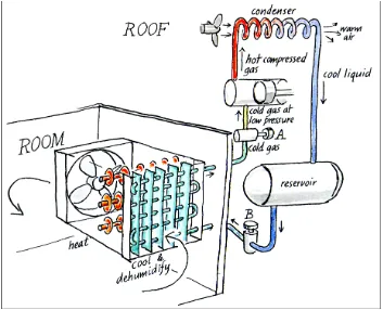
Figure 2.1: Minimal air conditioning. (The part of the system in the room, on the left, pulls air first over a cool surface and then over a warming surface. The part of the system on the right recirculates the cooling fluid. The fluid passes from the reservoir through a valve B into the lower pressure within the cooling unit in the room. There the liquid boils, removing heat from the air. The boiling point is fixed by the constant pressure set by valve A. The vapour is then compressed and condensed back into a liquid which collects in the reservoir ready for another cycle.)(Source: Tim Padfield, (2000))
The liquid is let into the cooling unit through a valve marked B on the diagram. It evaporates while it passes through the pipe, taking heat from the air. The temperature in the cooling coil depends partly on the amount of fluid let in by the valve, which is controlled by the thermostat or the humidistat. The minimum
temperature at the cold surface can be fixed by controlling the pressure in the cooling coil, with the valve marked A on the diagram. The boiling point of any liquid depends on the pressure. One could use water in the cooling coil, if the pressure is kept low enough. At 1000 Pa pressure, which seems a lot but is just 1% of atmospheric
7
The reason for wanting to limit the minimum temperature is to stop ice clogging the air passage. There are clever systems which notice when ice has formed and hold a melting pause, but that adds to the cost. The pressure controller is
therefore set to make the cooling fluid boil at the lowest temperature that is likely to be needed to control the humidity, but always over zero degrees. The temperature needed for cooling is nearly always higher than that needed for dehumidification so it is the RH setting that is decisive.
It is expensive to produce air at a dew point below about 4 degrees in this type of equipment. This dewpoint corresponds to 50% RH at 15°C. This sort of air
conditioning is entirely suitable for keeping people comfortable but it is not good for specialised stores, for films or for furs, for example, where one needs a temperature below 15 degrees. Such equipment is, however, often used for such places. A better solution is to use an absorption dehumidifier.
The vapour that emerges through the pressure controller is gathered up by a compressor. The compression also heats the gas. The hot gas is then led away from the room, to be cooled down. This is often done on the roof or in a small enclosure which vibrates to the roar of the fan blowing air over the fins of a condenser. The cooled, now liquid coolant is piped back to the reservoir, ready for its next tour through the room air conditioner.
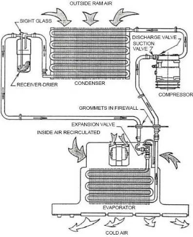
2.1 Automotive Air Conditioning Systems
Since the advent of the automotive air conditioning system in the 1940's, many things have undergone extensive change. Improvements, such as computerized automatic temperature control (which allow to set the desired temperature and have the system adjust automatically) and improvements to overall durability, have added complexity to today's modern air conditioning system.
To add to the complications, we now have tough environmental regulations that govern the very simplest of tasks, such as recharging the system with refrigerant R12 commonly referred to as Freon® (Freon is the trade name for the refrigerant R-12, that was manufactured by DuPont). Extensive scientific studies have proven the damaging effects of this refrigerant to our ozone layer, and its manufacture has been banned by the U.S. and many other countries that have joined together to sign the Montreal Protocol, a landmark agreement that was introduced in the 1980's to limit the production and use of chemicals known to deplete the ozone layer.
9
2.1.1 Compressor
Commonly referred to as the heart of the system, the compressor is a belt driven pump that is fastened to the engine. It is responsible for compressing and transferring refrigerant gas. The A/C system is split into two sides, a high pressure side and a low pressure side; defined as discharge and suction. Since the compressor is basically a pump, it must have an intake side and a discharge side. The intake, or suction side, draws in refrigerant gas from the outlet of the evaporator. In some cases it does this via the accumulator. Once the refrigerant is drawn into the suction side, it is
compressed and sent to the condenser, where it can then transfer the heat that is absorbed from the inside of the vehicle.
2.1.2 Condenser
This is the area in which heat dissipation occurs. The condenser, in many cases, will have much the same appearance as the radiator in you car as the two have very similar functions. The condenser is designed to radiate heat. Its location is usually in front of the radiator, but in some cases, due to aerodynamic improvements to the body of a vehicle, its location may differ. Condensers must have good air flow anytime the system is in operation. On rear wheel drive vehicles, this is usually accomplished by taking advantage of your existing engine's cooling fan. On front wheel drive vehicles, condenser air flow is supplemented with one or more electric cooling fan(s).As hot compressed gasses are introduced into the top of the condenser, they are cooled off. As the gas cools, it condenses and exits the bottom of the
condenser as a high pressure liquid. .
2.1.3 Evaporator
warmer air travels through the aluminum fins of the cooler evaporator coil, the moisture contained in the air condenses on its surface. Dust and pollen passing through stick to its wet surfaces and drain off to the outside. On humid days you may have seen this as water dripping from the bottom of your vehicle. Rest assured this is perfectly normal. The ideal temperature of the evaporator is 32° Fahrenheit or 0° Celsius. Refrigerant enters the bottom of the evaporator as a low pressure liquid. The warm air passing through the evaporator fins causes the refrigerant to boil
(refrigerants have very low boiling points). As the refrigerant begins to boil, it can absorb large amounts of heat. This heat is then carried off with the refrigerant to the outside of the vehicle. Several other components work in conjunction with the
evaporator. As mentioned above, the ideal temperature for an evaporator coil is 32° F. Temperature and pressure regulating devices must be used to control its temperature. While there are many variations of devices used, their main functions are the same; keeping pressure in the evaporator low and keeping the evaporator from freezing; A frozen evaporator coil will not absorb as much heat.
2.1.4 Pressure regulating devices
Controlling the evaporator temperature can be accomplished by controlling refrigerant pressure and flow into the evaporator. Many variations of pressure regulators have been introduced since the 1940's:
a. Orifice tube