OFFICE INTELLIGENT SYSTEM (OIS)
Kamaruddin bin Hammade
“I hereby declared that I have read through this report entitle “Office Intelligent System (OIS)” and found that it has comply the partial fulfillment for awarding the degree of Bachelor
of Electrical Engineering (Control, Instrument and Automation)
Signature : ………...
Supervisor’s name : ………
ii
OFFICE INTELLIGENT SYSTEM (OIS)
KAMARUDDIN BIN HAMMADE
A Report Submitted In Partial Fulfillment of Requirements for the Degree of Bachelor In Electrical Engineering (Control, Instrument and Automation)
Faculty of Electrical Engineering
UNIVERSITI TEKNIKAL MALAYSIA MELAKA
iii
“I declare that this report entitle “Office Intelligent System (OIS)” is the result of my own
research except as cited in the references. The report has not been accepted for any degree and is not concurrently submitted in candidature of any other degree.
Signature : ………..
Name : KAMARUDDIN BIN HAMMADE
iv
Specially dedicated to
v
ACKNOWLEDGEMENT
In the name of Allah, The Beneficent, The Merciful. Firstly and foremost, I would like to heartfelt thanks to mu supervisor, En Ahmad Zubir Bin Jamil for his endless support, invaluable guidance and critical comments throughout the project.
Next, my heartiest thanks to my wonderful family especially my parents Hammade Bin Nenga and Nurmah Binti Sattare who always pray for my success continuously, giving me all the guidance and supports that I needs all the time, you are source of inspire of my life
Not forgotten, all my friends especially from Electrical Engineering Course which is always give me their assistance and guidance to finish up this entire project.
vi
ABSTRACT
vii
ABSTRAK
viii
TABLE OF CONTENTS
CHAPTER CONTENT PAGE
ACKNOWLEDGEMENT ABSTRACT
ABSTRAK
TABLE OF CONTENTS LIST OF TABLES
LIST OF FIGURES
LIST OF APPENDICES
1 PROJECT BACKGROUND 1
1.1 Introduction 1
1.2 Objective of Project 1
1.3 Scope of project 2
1.4 Problem Statement 2
1.4.1 Waste in energy consumption 2 especially electricity
1.4.2 Thief, fire could not properly 3 be monitored .
1.4.3 Hardwire not really secure 3
2 LITERATURE REVIEW 2
2.1 Introduction 2
2.2 Interfacing System 5
2.2.1 IC ULN 2803 Pinout & Working 6
ix
2.2.2.1 Communicating with the Parallel Port 9
2.3 Graphical User Interface (GUI) 12
2.4 Visual Basic 6.0 (VB) 12
2.4.1 The Visual Basic Environment 13
2.4.2 The Control Properties 15
2.4.3 Handling some of the common controls 17
2.5 TVicLPT Overview 21
3 PROJECT METHODOLOGY 22
3.1 Methodology 22
3.2 Literature Review 23
3.3 Construct Modeling Office 24
3.4 Software Development Using Visual Basic (VB) 29
3.4.1 Login Page 31
3.4.1.1 Login Form 31
3.4.1.2Splash Screen Form 33
3.4.2 Main Page 35
3.4.2.1 Monitoring and Control System 35
3.4.2.2 Database System 39
3.4.2.3 CCTV System 43
3.4.2.3.1 ActiveX Control 43
3.4.2.3.2 Video Settings 45
4.3.2.3.3 Playback video 47
3.4.2.3.4 Picture Viewer 49
3.5 Wiring Of Hardware 50
3.5.1 Power Supply Unit (PSU) 51
3.5.2 Digital Code Lock (Code Access) 53
3.5.3 Interfacing Circuit 55
x
4 RESULTS AND DISCUSSION 60
4.1 Graphical User Interface (GUI) 60
4.1.1 GUI Main page 61
4.1.1.1 Module Coding for Main Page 63
4.1.2 Database System 64
4.1.3 CCTV System 66
4.2 Hardware Development 67
4.3 Testing Hardware and Software 69
4.3.1 Interface Testing Between Hardware and Software 69
4.3.2 Testing Input Address 70
4.4 Discussion 75
4.4.1 Analysis the output coding 75
5 CONCLUSION AND RECOMMENDATION 78
5.1 CONCLUSION 78
5.2 RECOMMENDATION 78
REFERENCES 79
xi
LIST OF TABLES
NO. TITLE PAGE
2.1 Parallel Port 25 pins 11
3.1 Power Supply Component 51
3.2 Digital Code Lock Components 53
3.3 Interface Components 55
4.1 List of reading status port 74
xii
LIST OF FIGURE
NO. TITLE PAGE
2.1 Block Diagram OIS 4
2.2 A complete block diagram of OIS and its monitoring 5
and control system.
2.3 Input/Output Module Interface Circuit 5
2.4 IC ULN 2803 Pinout 6
2.5 Pin connections 7
2.6 NPN Darlington 7
2.7 Darlington pair 8
2.8 Graph Power (Watt) vs Temperature (oC) 9
2.9 Parallel Port (25 pins) 10
2.10 Graphical User Interface System 12
2.11 The Visual Basic Start-up Dialog Box 13
2.12 The Visual Basic Environment 12
2.13 Typical properties window 16
2.14 General components 18
3.1 Project Flowchart 23
3.2 First Floor 25
3.3 Second Floor 26
3.4 Side view 27
3.5 Top view 27
3.6 Receiptionist 28
3.7 Front view 28
3.8 Flowchart of Visual Basic Development 30
xiii
3.10 Login successful 32
3.11 Error login 32
3.12 Splash screen form 33
3.13 Loading Form 34
3.14 Three main parts (System, Database and CCTV) 35
3.15 First Floor 36
3.16 Second Floor 36
3.17 Part of system 37
3.18 Database System OIS2009 39
3.19 Microsoft ADO Data Control 6.0 (OLEDB) 40
3.20 OIS Table 40
3.21 Properties Adodc1 40
3.22 Property Pages 41
3.23 Data Link Properties 41
3.24 ezVidCap Component and the video 43
3.25 Dialog box to record video 44
3.26 Save as video 44
3.27 Save as picture 44
3.28 Video Compression 45
3.29 Video Source (Device Setting) 46
3.30 Video Source (Capture Source) 46
3.31 Playback Video 47
3.32 ezVid File Dialog 47
3.33 Picture Viewer 49
3.34 Open Picture 49
3.35 Power Supply Unit 51
3.36 Power Supply Circuit 52
3.37 Code Access 53
3.38 Digital Code Access Circuit 54
3.39 Parallel Port and Cable 55
xiv
3.41 Interfacing Circuit 56
3.42 ON/OFF switch 57
3.43 Fan (Air-conditioner) 57
3.44 Lamp 57
3.45 Hardware (office model) 58
3.46 Hardware Circuit 59
4.1 Login System 60
4.2 Login successful 61
4.3 Splash screen form 61
4.4 Main page (first floor) 62
4.5 Main page (second floor) 62
4.6 Database System OIS2009 64
4.7 Office Intelligent System Database 65
4.8 CCTV System 66
4.9 Hardware 67
4.10 Power supply and switch box 67
4.11 Digital code access 68
4.12 Hardware testing 69
4.13 Interface testing 69
4.14 New project name 70
4.15 Drag Button 1 70
4.16 Drag Button 2 71
4.17 Port Testing 72
4.18 Popup window 72
4.19 Not connected 73
4.20 Ground connected with S7 73
4.21 Ground connected with S5 73
xv
LIST OF APPENDICES
APPENDIX TITLE PAGE
A Monitor and Control System Coding 80
B Database System Coding 86
C CCTV System Coding 88
CHAPTER 1
PROJECT BACKGROUND
1.1 Introduction
Basically an office intelligent system is the incorporation of information technology and communication system to make office more secure, easy to live, productive and cost effective. Various products of office intelligent system has emerged over the past years. Most of the product centers around using the facilities provided by the internet, mobile phones, telephones and various mean of communication to control some application in the office remotely, such as lighting television etc. Also most office intelligent system are also equipped with surveillance cameras for office owners to check their office visually using web browser. There are many more areas which need to be improved to make it safer, easier to live in, energy saving etc.
1.2 Objective of Project
The objectives of this project are:
i. To design and develop smart/intelligent system that consists of features: Time Controlled ; Lighting and Air-conditioner
Security System; Door access, CCTV and Alarm for fire-detector. GUI ; Monitoring and Control
Input/output Module Interface Circuit (Parallel Port);
2
1.3 Scope of project
The scope of this project covers two main parts, hardware and software. For the hardware, it includes design and constructs model office hardware and indentifies facilities such as lighting, computerized fire alarm monitoring system, Air-conditioner, Security
System (CCTV and door access using code access), Alarm for fire-detector and other typical facilities. All these facilities can be controlled either manually or by software control.
On the software sides, the type of controller will be indentified. Here, Graphical User Interface (GUI) developing using Visual Basic (VB). Programming Visual Basic also use to program time setting of each facility. Interfacing between both hardware and software are using Input/output Module Interface Circuit.
1.4 Problem Statement
1.4.1 Waste in energy consumption especially electricity
The energy consumption of electricity in office is greater and highest than at home. It because not have always supervise like at home, where at home had parents to supervise electricity consumption. At office, waste in electricity consumption always happen because
time usage the electricity not have person to guard. Attitude of staffs in the office that no care about economically electricity consumption is one factor of this problem none stop. Careless to switch off all the electrical facilities like lamp, air-conditioner, and others also is the factor of this problem. So, this project (OIS) will be solving the problem. This system can switch on all the facilities office in time of work and switch off the facilities
3
1.4.2 Thief, fire could not properly be monitored
Now, thief and fire problem can always happen at everywhere especially at office. This problem happens because they do not have control centre to properly monitor overall office every time. So, this OIS system will use CCTV to monitor overall area of office
meanwhile fire alarm detector used to detect the fire/smoke and give alarm signal. For the security system, door access will be used to avoid robbery happened.
1.4.3 Hardwire not really secure.
CHAPTER 2
LITERATURE REVIEW
2.1 Introduction
Figure below shows a block diagram Office Intelligent System (OIS). This block consists of 4 parts:
i. Hardware consists of facilities such as: Lighting
Computerized fire alarm monitoring system Air-conditioner
Security System (alarm and CCTV), door access (code access)
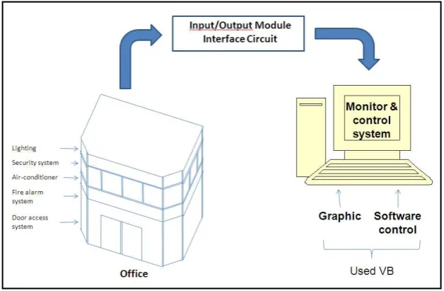
[image:20.595.148.462.488.693.2]ii. Interfacing System (Input/output Module Interface Circuit) iii. GUI System and time setting (Visual Basic)
5
2.2 Interfacing System
Use Input/output Module Interface Circuit. Parallel port 25 pin.
[image:21.595.145.466.197.391.2] Its function to interface between hardware and software.
Figure 2.2: A complete block diagram of OIS and its monitoring and control system.
[image:21.595.95.514.438.732.2]6
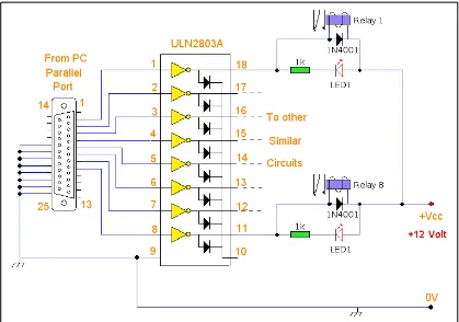
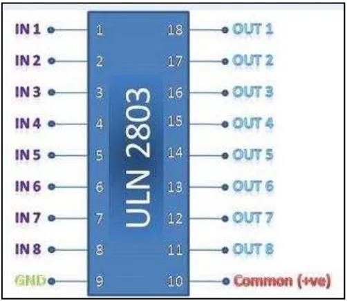
2.2.1 IC ULN 2803 Pinout & Working
IC ULN2803 consists of octal high voltage, high current Darlington transistor arrays. The eight NPN Darlington connected transistors in this family of arrays are ideally suited for interfacing between low logic level digital circuitry (such as TTL, CMOS or
PMOS/NMOS) and the higher current/voltage requirements of lamps, relays, printer hammers or other similar loads for a broad range of computer, industrial, and consumer applications.
Features:
Eight Darlingtons with Common Emitter Open–collector outputs
Freewheeling clamp diodes for transient suppression Output Current to 500 mA
Output Voltage to 50 V
[image:22.595.179.430.447.665.2] Inputs pinned opposite outputs to simplify board layout
7
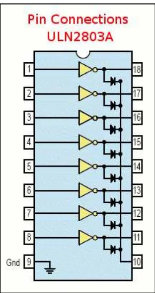
Figure 2.5: Pin connections
Working
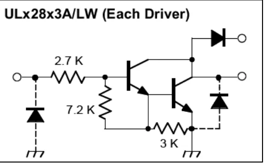
The ULN 2803 IC consists of eight NPN Darlington connected transistors (often called a Darlington pair). Darlington pair consists of two bipolar transistors such that the current amplified by the first is amplified further by the second to get a high current gain β or hFE. The figure shown below is one of the eight Darlington pairs of ULN 2803 IC.
[image:23.595.170.439.556.734.2]8
Figure 2.7: Darlington pair
Now two cases arise:
Case 1: When IN is 0 volts
Q1 and Q2 both will not conduct as there is no base current provided to them. Thus, nothing will appear at the output (OUT).
Case 2: When IN is 5 volts
Input current will increase and both transistors Q1 and Q2 will begin to conduct. Now, input current of Q2 is combination of input current and emitter current of Q1, so Q2 will conduct more than Q1 resulting in higher current gain which is very much required to
meet the higher current requirements of devices like motors, relays etc. Output current flows through Q2 providing a path (sink) to ground for the external circuit that the output is applied to. Thus, when a 5V input is applied to any of the input pins (1 to 8), output voltage at corresponding output pin (11 to 18) drops down to zero providing GND for the